 Probe

RATOPUS ACDC STAGE
OHWR0089 · revision R2
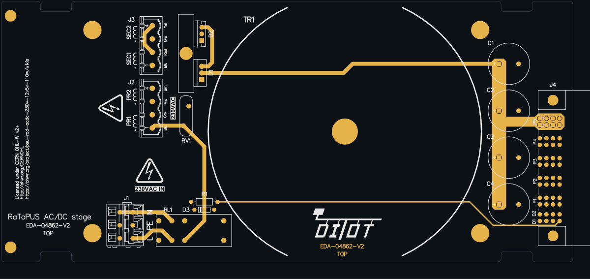
RATOPUS ACDC STAGE (OHWR0089 R2) is an open-hardware circuit board from its public repository, designed in Altium Designer: a 2-layer board of 219.6 × 100 mm with 18 components and 13 nets, published under CERN-OHL-W-2.0.
review 96% walked · 4 findings: 1 blocker · 1 major · 2 minor (5 items)
Open in the interactive viewerRead the full review
Design review
Probe recorded 4 findings: 1 blocker · 1 major · 2 minor (5 items) on this design. Each is shown here with its reasoning; the full review links every one to the pins, nets and datasheet pages it rests on.
- NetCopperSplitblockerOpen
L''s copper is in 2 pieces: J1.1 is not connected to the rest of the net
L''s copper is in 2 pieces: J1.1 is not connected to the rest of the net. Piece 1: RL1.21, on TOP_LAYER and BOTTOM_LAYER, 1 drill(s), over (126.04, 84.25) to (142.94, 89.75). Piece 2: J1.1, on TOP_LAYER and BOTTOM_LAYER, 1 drill(s), over (121.04, 85.1) to (127.84, 86.9). The export files every one of these pins under the net, so every connectivity check passes; the copper the fab builds leaves them apart. Usually a pour island that touches only one via of its own net, or a track ending short of its copper: join the piece to the net and export again.
At split:L'
- AssemblySeammajorOpen
AssemblySeam: 2 nets×2
e.g. “Nothing sources DC_RTN1 (OHWR-DIOT-CRATE-V3)” · 2 different statements
At VRECT
Each finding, with its own headline
VRECTNothing sources DC_RTN1 (OHWR-DIOT-CRATE-V3)
Every board this rail reaches receives it (PBP DC_RTN1, ACDC0 VRECT, PSU0 P24V), no declared member sources it, and it leaves the build through no other connector.
Found by the seam review of OHWR-DIOT-CRATE-V3 build 2 (M9-rail-direction, across seam:16, seam:18), where this board sits as ACDC0. On the assembly it is STALE: decided refuted by Claude interconnect reviewer (Cern session): Refuted for the real crate. DC_RTN1 carries VRECT (+24 V) of the RaToPUSv2 AC/DC stage seated as ACDC0, produced on that board by the D1 (DST2080C) / D2 (DSTF3060CR) full-wave bridge from the 2x 18 V secondaries of its off-board toroid TR1 (Multicomp MCTA160/18), which enter on its J3 (CERN schematic EDA-04862-V2-0 sheet 1). The transformer is now seated as declared member TR0 (supply, no copper). No MCTA160/18 datasheet or pinout is on file, so no connection diagram is declared and the engine cannot see it source; in addition the bridge rule does not admit VRECT (CERN BUG-072). The polarity of this feed against spec Table 3 is raised separately in OBS-581.
VRECTNothing sources DC_RTN2 (OHWR-DIOT-CRATE-V3)
Every board this rail reaches receives it (PBP DC_RTN2, ACDC1 VRECT, PSU1 P24V), no declared member sources it, and it leaves the build through no other connector.
Found by the seam review of OHWR-DIOT-CRATE-V3 build 2 (M9-rail-direction, across seam:17, seam:19), where this board sits as ACDC1. On the assembly it is STALE: decided refuted by Claude interconnect reviewer (Cern session): Refuted for the real crate. DC_RTN2 carries VRECT (+24 V) of the RaToPUSv2 AC/DC stage seated as ACDC1, produced on that board by the D1 (DST2080C) / D2 (DSTF3060CR) full-wave bridge from the 2x 18 V secondaries of its off-board toroid TR1 (Multicomp MCTA160/18), which enter on its J3 (CERN schematic EDA-04862-V2-0 sheet 1). The transformer is now seated as declared member TR1 (supply, no copper). No MCTA160/18 datasheet or pinout is on file, so no connection diagram is declared and the engine cannot see it source; in addition the bridge rule does not admit VRECT (CERN BUG-072). The polarity of this feed against spec Table 3 is raised separately in OBS-581.
RaToPUSv2 puts +24 V on the back-panel contact the DI/OT Crate spec names DC_RTN, and GND on DC_IN
J4 of the RaToPUS AC/DC Stage drives its rectified +24 V (VRECT) onto PwrBlade contact P5, which the DI/OT Crate spec v3.1 Table 3 names DC_RTN, and ties P4 (DC_IN) to GND: the polarity is the reverse of the names, so a back-panel DC feed wired to Table 3 would reach a RaToPUS DC/DC Stage reversed.
The contacts against the spec
Contact DI/OT Crate spec v3.1, Table 3 (p. 9) OHWR0089 R2 RATOPUS ACDC STAGE, J4 (sheet 1) OHWR0088 R5 RATOPUS DCDC STAGE, J4 (sheet 7) P4 DC_IN GND GND P5 DC_RTN VRECT (+24 V rectified) P24V (its 24 V input) The OHWR0085 R4 DIOT CRATE POWER BACKPLANE carries both contacts straight through on nets DC_IN1/DC_RTN1 (J5.P4/P5 back panel to J1.P4/P5 front slot), as §3.2 item 4 describes ("directly wired").
``
mermaid flowchart LR A["AC/DC Stage J4<br/>P5 = VRECT (+24 V)<br/>P4 = GND"] -->|"P5 on net DC_RTN1<br/>P4 on net DC_IN1"| B["Power Backplane<br/>J5 to J1"] B --> C["DC/DC Stage J4<br/>P5 = P24V<br/>P4 = GND"]``Why it matters
The two RaToPUSv2 stages agree with each other, so a rad-tol crate built from them powers up correctly. The spec, though, presents DC_IN/DC_RTN as the inlet for "full DC powering" (24 VDC or 48 VDC) from a back-panel module. A back-panel DC module built to the names in Table 3 (positive on DC_IN, return on DC_RTN) and fitted behind a RaToPUS DC/DC Stage would apply its supply reversed. Either the spec's labels or the boards' polarity needs aligning, or the convention needs stating in Table 3.
RV1 S14K250 is rated 250 V RMS continuous, below the 253 V upper tolerance of 230 V mains
RV1 (TDK/EPCOS S14K250) sits across the switched 230 VAC mains L–N, and its maximum continuous rating of 250 V RMS is below the usual +10 % upper limit of 230 V mains (253 V RMS). A varistor run at or above its continuous rating heats and ages faster.
Ratings against the line
Quantity Value Source Line 230 V AC mains, L–N after relay RL1 CERN sheet 1: J1 "230VAC IN", RV1 labelled "250VAC" Mains upper tolerance 230 V + 10 % = 253 V RMS IEC 60038 supply tolerance ±10 % (cited, not held) RV1 max. continuous V_RMS 250 V TDK B722* datasheet p.9, Maximum ratings (TA = 105 °C), row B72214S0251K101 / S14K250 Same size, next rating up S14K275: 275 V RMS; V_v 430 V; v_c 710 V at 50 A same datasheet p.9 / p.10 RV1 varistor voltage / clamp 390 V ±10 % / 650 V at 50 A same datasheet p.10 For CERN to confirm
Is 250 V the intended continuous rating, for example to keep the clamp at 650 V rather than 710 V? Or should RV1 be the 275 V part usually chosen for 230 V mains? The protected element is the MCTA160/18 toroid on J2, which publishes no surge rating.
Placement and return are sound: both L and N route through RV1's pads about 13 mm before J2, and it clamps line to line.
Main parts
| Part number | Maker | Description | Where |
|---|---|---|---|
| 1N916 | ON SEMICONDUCTOR | Diode | D3 |
| 236-403 | WAGO | Terminal Block, 3 Positions, Screw Connection | J1 |
| 40.52.7.024.0000 | FINDER | 8A DPDT PCB Relay, 40.52 Serie | RL1 |
| 51939-576 | AMPHENOL | Thru-Hole, Lead 3.43mm, PowerBlade Right Angled Power Connector 8S 5ACP Contacts | J4 |
| B72214S0251K101 or S14K250 | EPCOS / TDK | Varistor | RV1 |
| DST2080C | LITTELFUSE | Dual Common Cathode Diodes | D1 |
| DSTF3060CR | LITTELFUSE | Dual Common Anode Diodes | D2 |
| RMF_10R_1%_0.6W_50PPM_1016-630X250 | GENERIC | Resistor - 1% | R1 |
| 1755752 (MSTBVA 2,5/ 4-G-5,08) | PHOENIX CONTACT | Connector 4 Male | J2, J3 |
| EEU-FR1V222B | PANASONIC | Polarised capacitor | C1, C2, C3, C4 |
About this design
- Design
- RATOPUS ACDC STAGE — OHWR0089 R2
- Designed in
- Altium Designer
- Board
- 2 copper layers, 219.6 × 100 mm, 18 components, 13 nets
- Licence
- CERN-OHL-W-2.0
- Source
- https://edms.cern.ch/item/EDA-04862-V2-0/0 at commit
EDMS EDA-048 - Attribution
- CERN EDMS item EDA-04862-V2-0 'RaToPUS AC/DC Stage': document 3151225 v.1, retrieved 2026-10-18T13:12:22Z. CERN EDA-04862 V2, RaToPUS AC/DC Stage (RaToPUSv2). Copyright CERN 2023, 2024. Licence: CERN OHL-W v2.0+. Source location: https://ohwr.org/project/psu-rad-acdc-230v-12v5v-110w/wikis
- Reviewed with
- Probe by E# (E-Sharp AB)