 Probe

WRS V3 SCB
OHWR0012 · revision R1
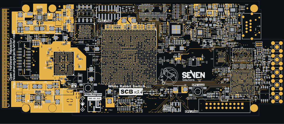
WRS V3 SCB (OHWR0012 R1) is an open-hardware circuit board from the CERN Open Hardware Repository, designed in Altium Designer: a 12-layer board of 180.6 × 73.5 mm with 767 components and 906 nets, published under CERN-OHL-1.2.
review 82% walked · 22 findings: 1 blocker · 9 major · 12 minor (78 items)
Open in the interactive viewerRead the full review
Design review
Probe recorded 22 findings: 1 blocker · 9 major · 12 minor (78 items) on this design. Each is shown here with its reasoning; the full review links every one to the pins, nets and datasheet pages it rests on.
- NetCopperSplitblockerOpen
NetCopperSplit: 4 boards×4
e.g. “+2V5's copper is in 2 pieces: C268.1 and C271.1 are not connected to the rest of the net” · 4 different statements
At split:+2V5, split:GND, split:GND_SHIELD, split:NetC160_1
Each finding, with its own headline
split:+2V5+2V5's copper is in 2 pieces: C268.1 and C271.1 are not connected to the rest of the net
+2V5's copper is in 2 pieces: C268.1 and C271.1 are not connected to the rest of the net. Piece 1: C1.2, C11.1, C13.1, C210.2, C211.2, C259.1, C260.1, C269.2 and 145 more pin(s), on TOP_LAYER, MIDLAYER1, MIDLAYER2, MIDLAYER3, MIDLAYER4 and BOTTOM_LAYER, 117 drill(s), 56.21 mm2 of pour, over (10.25, -35.02) to (171.42, 34.95). Piece 2: C268.1 and C271.1, on TOP_LAYER, over (10.25, -18.83) to (13.55, -17.78). The export files every one of these pins under the net, so every connectivity check passes; the copper the fab builds leaves them apart. Usually a pour island that touches only one via of its own net, or a track ending short of its copper: join the piece to the net and export again.
split:GNDGND's copper is in 4 pieces: C45.1 and 2 other piece(s) are not connected to the rest of the net
GND's copper is in 4 pieces: C45.1 and 2 other piece(s) are not connected to the rest of the net. Piece 1: C1.1, C10.1, C100.1, C104.1, C105.2, C106.1, C107.2, C108.1 and 923 more pin(s), on TOP_LAYER, MIDLAYER1, MIDLAYER2, MIDLAYER3, MIDLAYER4 and BOTTOM_LAYER, 708 drill(s), 1956.13 mm2 of pour, over (0.7, -35.04) to (175.35, 35). Piece 2: C45.1, on BOTTOM_LAYER, over (113.06, -2.66) to (113.68, -2.04). Piece 3: C169.1, on BOTTOM_LAYER, over (111.54, 21.94) to (112.16, 22.56). Piece 4: C43.2, on BOTTOM_LAYER, over (114.22, -2.67) to (114.84, -2.05). The export files every one of these pins under the net, so every connectivity check passes; the copper the fab builds leaves them apart. Usually a pour island that touches only one via of its own net, or a track ending short of its copper: join the piece to the net and export again.
split:GND_SHIELDGND_SHIELD's copper is in 3 pieces: CN1.0 and 1 other piece(s) are not connected to the rest of the net
GND_SHIELD's copper is in 3 pieces: CN1.0 and 1 other piece(s) are not connected to the rest of the net. Piece 1: C214.2, on TOP_LAYER, MIDLAYER1, MIDLAYER2, MIDLAYER3, MIDLAYER4 and BOTTOM_LAYER, 1 drill(s), over (151.82, 22.01) to (155.82, 27.4). Piece 2: CN1.0, on TOP_LAYER, MIDLAYER1, MIDLAYER2, MIDLAYER3, MIDLAYER4 and BOTTOM_LAYER, 1 drill(s), over (154.12, 11.7) to (161.42, 29.4). Piece 3: L10.1, on TOP_LAYER, MIDLAYER1, MIDLAYER2, MIDLAYER3, MIDLAYER4 and BOTTOM_LAYER, 1 drill(s), over (159.5, 27.7) to (164.5, 34.5). The export files every one of these pins under the net, so every connectivity check passes; the copper the fab builds leaves them apart. Usually a pour island that touches only one via of its own net, or a track ending short of its copper: join the piece to the net and export again.
split:NetC160_1NetC160_1's copper is in 4 pieces: C161.2 and 2 other piece(s) are not connected to the rest of the net
NetC160_1's copper is in 4 pieces: C161.2 and 2 other piece(s) are not connected to the rest of the net. Piece 1: IC16.4 and L8.1, on TOP_LAYER, MIDLAYER1, MIDLAYER2, MIDLAYER3, MIDLAYER4 and BOTTOM_LAYER, 1 drill(s), over (107.25, 10.8) to (110.04, 15). Piece 2: C161.2, on BOTTOM_LAYER, over (108.95, 13.53) to (109.95, 14.48). Piece 3: C160.1, on BOTTOM_LAYER, over (110.54, 13.54) to (111.16, 14.16). Piece 4: C163.2, on BOTTOM_LAYER, over (110.54, 14.49) to (111.16, 15.11). The export files every one of these pins under the net, so every connectivity check passes; the copper the fab builds leaves them apart. Usually a pour island that touches only one via of its own net, or a track ending short of its copper: join the piece to the net and export again.
ARM_PCK0: the SAM9G45 drives a 2.5 V clock (PA31, VDDIOP0 = +2V5) straight into FPGA bank 15, which runs at 1.8 V; about 2.55 V against an absolute maximum of VCCO + 0.5 V = 2.24 V
ARM_PCK0 drives a 2.5 V clock from the SAM9G45 (PA31, VDDIOP0 = +2V5) straight into Virtex-6 bank 15, which runs at 1.8 V: about 2.55 V against an absolute maximum of VCCO + 0.5 V = 2.24 V.
Where it is
Net ARM_PCK0 connects AT91SAM9G45 ball V1 (PA31, MCI1_CK / PCK0) directly to Virtex-6 ball N33 (IO_L10P_MRCC_15), with no series resistor, divider or level shifting.
``
mermaid flowchart LR A["IC6 SAM9G45 V1<br/>PA31 PCK0, VDDIOP0 +2V5"] -- "ARM_PCK0, no resistor" --> F["IC33 Virtex-6 N33<br/>bank 15, VCCO +1V8"]``The numbers
Quantity Value Source PA31 I/O supply VDDIOP0 SAM9G45 datasheet, p.25 VDDIOP0 on this board, +2V5 about 2.55 V IC47 VFB2 divider Bank 15 VCCO, +1V8 about 1.74 V IC47 VFB1, R241 13K / R242 10K Absolute maximum input, 2.5 V-or-below I/O VCCO + 0.5 V = 2.24 V DS152 Table 1 Recommended maximum VCCO + 0.2 V DS152 Table 2 Clamp diode forward current limit 10 mA DS152 Table 2 N33 bank IO_L10P_MRCC_15, bank 15 UG365 Table 2-5, p.148 When firmware enables PCK0 (or MCI1_CK) as an output, the FPGA input sees about 2.55 V. The only thing between the two is the FPGA clamp diode, and nothing on the board limits its current.
Why this one stands out
Every other 2.5 V ARM signal into the FPGA (IRQ/FIQ, SPI1, the configuration lines, ARM_FPGA_RESET) lands in a +2V5 bank, and the 1.8 V EBI1 signals come from the 1.8 V VDDIOM1 domain. This one clock is the exception.
- NetCopperSplitmajorOpen
+5VCC_IN's copper is in 2 pieces joined only through T4: T4.6 is connected only if the part bonds its pins inside
+5VCC_IN's copper is in 2 pieces joined only through T4: T4.6 is connected only if the part bonds its pins inside. Piece 1: C239.1, C248.1, C249.1, C251.2, C254.1, C255.2, C257.1, C258.1 and 43 more pin(s), on TOP_LAYER, MIDLAYER1, MIDLAYER2, MIDLAYER3, MIDLAYER4 and BOTTOM_LAYER, 43 drill(s), 314.71 mm2 of pour, over (9.95, -34.94) to (150.19, 34.9). Piece 2: T4.6, on TOP_LAYER, over (13.53, -25.47) to (15.08, -24.87). Only T4 has pins in more than one piece; if those pins are bonded inside the package the net is whole, and if not, the copper leaves it open. A track or a via of the net joining the pieces closes it.
At split:+5VCC_IN
- DecapOrdermajorOpen
DecapOrder: 4 findings (2 components, 2 pins)×4
Checked by the review, stands · Claude walker W2 (Cern session) — Checked: the distances are read from placement and stand as stated. Which capacitor sits nearest a supply pin at the 1-5 mm scale is a layout heuristic (Probe's starting thresholds), not a requirement of the part's datasheet on file; at this scale via and plane-spreading inductance usually dominate. Left for the owner.
At IC33, IC33.A32, IC34.1, IC43
Each finding, with its own headline
IC33IC33 supply pins R12, R14, T11, U10 on '+1V0': the smallest capacitor C70 sits 4.6 mm away, behind C72 at 1.6 mm
IC33 supply pins R12, R14, T11, U10 on '+1V0': the smallest capacitor C70 sits 4.6 mm away, behind C72 at 1.6 mm. IC33.R12: the smallest value, C70 (470 nF), is 4.6 mm from the pin and C72 (4.7 uF) 1.6 mm: the high-frequency part sits behind more inductance than the bulk part, which needs it least. IC33.R14: the smallest value, C70 (470 nF), is 4.8 mm from the pin and C71 (4.7 uF) 2.4 mm: the high-frequency part sits behind more inductance than the bulk part, which needs it least. IC33.T11: the smallest value, C70 (470 nF), is 3.8 mm from the pin and C72 (4.7 uF) 1.0 mm: the high-frequency part sits behind more inductance than the bulk part, which needs it least. IC33.U10: the smallest value, C70 (470 nF), is 3.5 mm from the pin and C72 (4.7 uF) 1.8 mm: the high-frequency part sits behind more inductance than the bulk part, which needs it least. Swap them, or bring the smallest value to the pin: it serves the fastest current and is the one the loop inductance defeats. Distances are pad centre to pin centre in the board plane. The 5 mm radius, the 10x value step and the 1 mm / 1.5x tie tolerance are Probe's starting values.
IC33.A32IC33 supply pin A32 on '+1V8': the smallest capacitor C73 sits 3.0 mm away, behind C76 at 0.5 mm
IC33 supply pin A32 on '+1V8': the smallest capacitor C73 sits 3.0 mm away, behind C76 at 0.5 mm. IC33.A32: the smallest value, C73 (470 nF), is 3.0 mm from the pin and C76 (22 uF) 0.5 mm: the high-frequency part sits behind more inductance than the bulk part, which needs it least. Swap them, or bring the smallest value to the pin: it serves the fastest current and is the one the loop inductance defeats. Distances are pad centre to pin centre in the board plane. The 5 mm radius, the 10x value step and the 1 mm / 1.5x tie tolerance are Probe's starting values.
IC34.1IC34 supply pin 1 on '+3V3': the smallest capacitor C191 sits 4.8 mm away, behind C275 at 1.9 mm
IC34 supply pin 1 on '+3V3': the smallest capacitor C191 sits 4.8 mm away, behind C275 at 1.9 mm. IC34.1: the smallest value, C191 (100 nF), is 4.8 mm from the pin and C275 (4.7 uF) 1.9 mm: the high-frequency part sits behind more inductance than the bulk part, which needs it least. Swap them, or bring the smallest value to the pin: it serves the fastest current and is the one the loop inductance defeats. Distances are pad centre to pin centre in the board plane. The 5 mm radius, the 10x value step and the 1 mm / 1.5x tie tolerance are Probe's starting values.
IC43IC43 supply pins E4, E8, F4, F5, F8, H3, H9, K8, L8 on '+1V8': the smallest capacitor C351 sits 3.0 mm away, behind C348 at 1.2 mm
IC43 supply pins E4, E8, F4, F5, F8, H3, H9, K8, L8 on '+1V8': the smallest capacitor C351 sits 3.0 mm away, behind C348 at 1.2 mm. IC43.E4: the smallest value, C351 (1 nF), is 3.0 mm from the pin and C348 (100 nF) 1.2 mm: the high-frequency part sits behind more inductance than the bulk part, which needs it least. IC43.E8: the smallest value, C349 (1 nF), is 3.1 mm from the pin and C346 (100 nF) 0.8 mm: the high-frequency part sits behind more inductance than the bulk part, which needs it least. IC43.F4: the smallest value, C351 (1 nF), is 2.2 mm from the pin and C348 (100 nF) 0.5 mm: the high-frequency part sits behind more inductance than the bulk part, which needs it least. IC43.F5: the smallest value, C351 (1 nF), is 1.7 mm from the pin and C342 (100 nF) 0.5 mm: the high-frequency part sits behind more inductance than the bulk part, which needs it least. IC43.F8: the smallest value, C349 (1 nF), is 2.2 mm from the pin and C346 (100 nF) 0.6 mm: the high-frequency part sits behind more inductance than the bulk part, which needs it least. IC43.H3: the smallest value, C352 (1 nF), is 2.5 mm from the pin and C333 (22 nF) 0.1 mm: the high-frequency part sits behind more inductance than the bulk part, which needs it least. IC43.H9: the smallest value, C349 (1 nF), is 2.3 mm from the pin and C347 (100 nF) 0.5 mm: the high-frequency part sits behind more inductance than the bulk part, which needs it least. IC43.K8: the smallest value, C349 (1 nF), is 2.5 mm from the pin and C335 (22 nF) 0.4 mm: the high-frequency part sits behind more inductance than the bulk part, which needs it least. And 1 more pin(s) the same way. Swap them, or bring the smallest value to the pin: it serves the fastest current and is the one the loop inductance defeats. Distances are pad centre to pin centre in the board plane. The 5 mm radius, the 10x value step and the 1 mm / 1.5x tie tolerance are Probe's starting values.
- DecapViaFanoutmajorOpen
DecapViaFanout: 4 components×4
Checked by the review, stands · Claude walker W2 (Cern session) — Checked: the fanout length is read from the copper and stands; 0.5 nH is Probe's starting value, not a datasheet requirement. Whether it matters depends on the rail's PDN target, which is not stated. Left for the owner.
At C151, C213, C324, C412
Each finding, with its own headline
C151C151 on '+2V5_PLL': its rail pad reaches its via over 3.20 mm of track, adding about 1.11 nH to its loop, past Probe's 0.5 nH starting value; put the vias at the pads
C151 on '+2V5_PLL': its rail pad reaches its via over 3.20 mm of track, adding about 1.11 nH to its loop, past Probe's 0.5 nH starting value; put the vias at the pads. C151.2 (rail) runs 3.20 mm along its copper to its nearest via, 2.20 mm past the 1 mm beside the pad: 1.11 nH; C151.1 (ground) not measured: the pad sits in a pour of its net on its own layer, which has no track length to measure. Each run past the pad as one conductor of a pair 1.60 mm apart (the pad pitch), 0.2 l ln(D/R) nH with R 0.127 mm (the track's width is not read): 1.11 nH in all. Put the vias at the pads (or in them), one per pad at least, the rail's and the ground's close together; the capacitor's own inductance as mounted is 1.38 nH (pad 0.10 nH + no via of the first net within 1 mm of its pad: the study's 0.6 nH per mm of 1.29 mm depth, ASSUMED). 0.5 nH is Probe's starting value, about the whole mounted inductance of a well-mounted 0402.
C213C213 on '+3V3_PHY': its rail pad reaches its via over 2.73 mm of track and its ground pad over 1.98 mm, adding about 1.06 nH to its loop, past Probe's 0.5 nH starting value; put the vias at the pads
C213 on '+3V3_PHY': its rail pad reaches its via over 2.73 mm of track and its ground pad over 1.98 mm, adding about 1.06 nH to its loop, past Probe's 0.5 nH starting value; put the vias at the pads. C213.1 (rail) runs 2.73 mm along its copper to its nearest via, 1.73 mm past the 1 mm beside the pad: 0.68 nH; C213.2 (ground) runs 1.98 mm along its copper to its nearest via, 0.98 mm past the 1 mm beside the pad: 0.38 nH. Each run past the pad as one conductor of a pair 0.90 mm apart (the pad pitch), 0.2 l ln(D/R) nH with R 0.127 mm (the track's width is not read): 1.06 nH in all. Put the vias at the pads (or in them), one per pad at least, the rail's and the ground's close together; the capacitor's own inductance as mounted is 1.14 nH (pad 0.07 nH + no via of the first net within 1 mm of its pad: the study's 0.6 nH per mm of 1.29 mm depth, ASSUMED). 0.5 nH is Probe's starting value, about the whole mounted inductance of a well-mounted 0402.
C324C324 on '+1V8': its rail pad reaches its via over 0.63 mm of track and its ground pad over 3.38 mm, adding about 0.93 nH to its loop, past Probe's 0.5 nH starting value; put the vias at the pads
C324 on '+1V8': its rail pad reaches its via over 0.63 mm of track and its ground pad over 3.38 mm, adding about 0.93 nH to its loop, past Probe's 0.5 nH starting value; put the vias at the pads. C324.1 (rail) runs 0.63 mm along its copper to its nearest via, beside the pad; C324.2 (ground) runs 3.38 mm along its copper to its nearest via, 2.38 mm past the 1 mm beside the pad: 0.93 nH. Each run past the pad as one conductor of a pair 0.90 mm apart (the pad pitch), 0.2 l ln(D/R) nH with R 0.127 mm (the track's width is not read): 0.93 nH in all. Put the vias at the pads (or in them), one per pad at least, the rail's and the ground's close together; the capacitor's own inductance as mounted is 1.14 nH (pad 0.07 nH + no via of the second net within 1 mm of its pad: the study's 0.6 nH per mm of 1.29 mm depth, ASSUMED). 0.5 nH is Probe's starting value, about the whole mounted inductance of a well-mounted 0402.
C412C412 on 'QDRII_VTT': its rail pad reaches its via over 4.30 mm of track, adding about 1.29 nH to its loop, past Probe's 0.5 nH starting value; put the vias at the pads
C412 on 'QDRII_VTT': its rail pad reaches its via over 4.30 mm of track, adding about 1.29 nH to its loop, past Probe's 0.5 nH starting value; put the vias at the pads. C412.1 (rail) runs 4.30 mm along its copper to its nearest via, 3.30 mm past the 1 mm beside the pad: 1.29 nH; C412.2 (ground) not measured: the pad sits in a pour of its net on its own layer, which has no track length to measure. Each run past the pad as one conductor of a pair 0.90 mm apart (the pad pitch), 0.2 l ln(D/R) nH with R 0.127 mm (the track's width is not read): 1.29 nH in all. Put the vias at the pads (or in them), one per pad at least, the rail's and the ground's close together; the capacitor's own inductance as mounted is 1.18 nH (pad 0.07 nH + no via of the first net within 1 mm of its pad: the study's 0.6 nH per mm of 1.35 mm depth, ASSUMED). 0.5 nH is Probe's starting value, about the whole mounted inductance of a well-mounted 0402.
- AssemblySeammajorOpen
Nothing drives RS232_MNG.RS232_MNG_RXD (OHWR-WRS-V3)
SCB IC31.13 (RIN1) receive on this node, which spans SCB RS232_MNG.RS232_MNG_RXD; no fitted pin on any of those boards drives it and nothing pulls it, so the inputs float.
Found by the seam review of OHWR-WRS-V3 build 2 (M2-no-driver, across seam:4), where this board sits as SCB. Decide it here (disposition_finding forwards it to the assembly) or on the assembly (build id 2, kind
signal, ref signal:M2-no-driver:c45b8f1c4891a398), and the decision holds on both.At RS232_MNG.RS232_MNG_RXD
- PartLifecyclemajorOpen
PartLifecycle: 9 part numbers×9
7 Obsolete, 2 Discontinued at DigiKey · on 12 placements
At D16, IC12, IC21, IC25, IC28, IC43 and 3 more
Each finding, with its own headline
D16S2M-TP on D16: the distributor catalogue reports "Discontinued at DigiKey" for MCC (Micro Commercial Components)'s S2M-TP
S2M-TP on D16: the distributor catalogue reports "Discontinued at DigiKey" for MCC (Micro Commercial Components)'s S2M-TP — a sourcing/longevity risk to confirm against the MANUFACTURER before acting. This board's BOM names no manufacturer for it, so whether that is the fitted maker's product was not checked. A distributor delisting is not the same claim as the part being unavailable; check the vendor's own lifecycle/product-change notice for the status and any named successor. Re-read the source: GET /api/odb/parts/S2M-TP/providers (which provider said it, the maker and part number it matched, its own words, and when we asked). No approved alternate is recorded for this position.
IC12MC100LVEP14DT on IC12: the distributor catalogue reports "Obsolete" for onsemi's MC100LVEP14DT
MC100LVEP14DT on IC12: the distributor catalogue reports "Obsolete" for onsemi's MC100LVEP14DT — a sourcing/longevity risk to confirm against the MANUFACTURER before acting. This board's BOM names no manufacturer for it, so whether that is the fitted maker's product was not checked. A distributor delisting is not the same claim as the part being unavailable; check the vendor's own lifecycle/product-change notice for the status and any named successor. Re-read the source: GET /api/odb/parts/MC100LVEP14DT/providers (which provider said it, the maker and part number it matched, its own words, and when we asked). No approved alternate is recorded for this position.
IC21DS90LV011ATMF on IC21: the distributor catalogue reports "Obsolete" for Texas Instruments's DS90LV011ATMF
DS90LV011ATMF on IC21: the distributor catalogue reports "Obsolete" for Texas Instruments's DS90LV011ATMF — a sourcing/longevity risk to confirm against the MANUFACTURER before acting. This board's BOM names National Semiconductor, and that is one line with Texas Instruments: Texas Instruments completed its acquisition of National Semiconductor on 2011-09-23. A distributor delisting is not the same claim as the part being unavailable; check the vendor's own lifecycle/product-change notice for the status and any named successor. Re-read the source: GET /api/odb/parts/DS90LV011ATMF/providers (which provider said it, the maker and part number it matched, its own words, and when we asked). THE LAST BUY DATE HAS PASSED (2025-04-10, 584 day(s) ago), so this is a substitution rather than a buy. The distributor reports 59,366 left. No approved alternate is recorded for this position.
IC25AT45DB321D-MWU on IC25: the distributor catalogue reports "Obsolete" for Microchip Technology's AT45DB321D-MWU
AT45DB321D-MWU on IC25: the distributor catalogue reports "Obsolete" for Microchip Technology's AT45DB321D-MWU — a sourcing/longevity risk to confirm against the MANUFACTURER before acting. This board's BOM names no manufacturer for it, so whether that is the fitted maker's product was not checked. A distributor delisting is not the same claim as the part being unavailable; check the vendor's own lifecycle/product-change notice for the status and any named successor. Re-read the source: GET /api/odb/parts/AT45DB321D-MWU/providers (which provider said it, the maker and part number it matched, its own words, and when we asked). No approved alternate is recorded for this position.
IC28LM385M3-2.5 on IC28: the distributor catalogue reports "Obsolete" for Texas Instruments's LM385M3-2.5
LM385M3-2.5 on IC28: the distributor catalogue reports "Obsolete" for Texas Instruments's LM385M3-2.5 — a sourcing/longevity risk to confirm against the MANUFACTURER before acting. This board's BOM names National Semiconductor, and that is one line with Texas Instruments: Texas Instruments completed its acquisition of National Semiconductor on 2011-09-23. A distributor delisting is not the same claim as the part being unavailable; check the vendor's own lifecycle/product-change notice for the status and any named successor. Re-read the source: GET /api/odb/parts/LM385M3-2.5/providers (which provider said it, the maker and part number it matched, its own words, and when we asked). THE LAST BUY DATE HAS PASSED (2024-03-18, 972 day(s) ago), so this is a substitution rather than a buy. The distributor reports 450 left. No approved alternate is recorded for this position.
IC43CY7C1314KV18-250BZC on IC43: the distributor catalogue reports "Obsolete" for Infineon Technologies's CY7C1314KV18-250BZC
CY7C1314KV18-250BZC on IC43: the distributor catalogue reports "Obsolete" for Infineon Technologies's CY7C1314KV18-250BZC — a sourcing/longevity risk to confirm against the MANUFACTURER before acting. This board's BOM names no manufacturer for it, so whether that is the fitted maker's product was not checked. A distributor delisting is not the same claim as the part being unavailable; check the vendor's own lifecycle/product-change notice for the status and any named successor. Re-read the source: GET /api/odb/parts/CY7C1314KV18-250BZC/providers (which provider said it, the maker and part number it matched, its own words, and when we asked). THE LAST BUY DATE HAS PASSED (2024-08-18, 819 day(s) ago), so this is a substitution rather than a buy. No approved alternate is recorded for this position.
IC50MT47H32M16HR-25E:G on IC50: the distributor catalogue reports "Obsolete" for Micron Technology Inc.'s MT47H32M16HR-25E:G
MT47H32M16HR-25E:G on IC50: the distributor catalogue reports "Obsolete" for Micron Technology Inc.'s MT47H32M16HR-25E:G — a sourcing/longevity risk to confirm against the MANUFACTURER before acting. This board's BOM names no manufacturer for it, so whether that is the fitted maker's product was not checked. A distributor delisting is not the same claim as the part being unavailable; check the vendor's own lifecycle/product-change notice for the status and any named successor. Re-read the source: GET /api/odb/parts/MT47H32M16HR-25E:G/providers (which provider said it, the maker and part number it matched, its own words, and when we asked). THE LAST BUY DATE HAS PASSED (2015-02-28, 4,278 day(s) ago), so this is a substitution rather than a buy. The distributor reports NONE left. No approved alternate is recorded for this position.
IC6AT91SAM9G45-CU on IC6: the distributor catalogue reports "Obsolete" for Microchip Technology's AT91SAM9G45-CU
AT91SAM9G45-CU on IC6: the distributor catalogue reports "Obsolete" for Microchip Technology's AT91SAM9G45-CU — a sourcing/longevity risk to confirm against the MANUFACTURER before acting. This board's BOM names no manufacturer for it, so whether that is the fitted maker's product was not checked. A distributor delisting is not the same claim as the part being unavailable; check the vendor's own lifecycle/product-change notice for the status and any named successor. Re-read the source: GET /api/odb/parts/AT91SAM9G45-CU/providers (which provider said it, the maker and part number it matched, its own words, and when we asked). THE LAST BUY DATE HAS PASSED (2013-09-01, 4,823 day(s) ago), so this is a substitution rather than a buy. The distributor reports NONE left. No approved alternate is recorded for this position.
T2IRF9910Pbf on 4 placements (T2, T3, T4, T5): the distributor catalogue reports "Discontinued at DigiKey" for Infineon Technologies's IRF9910PBF
IRF9910Pbf on 4 placements (T2, T3, T4, T5): the distributor catalogue reports "Discontinued at DigiKey" for Infineon Technologies's IRF9910PBF — a sourcing/longevity risk to confirm against the MANUFACTURER before acting. This board's BOM names INTERNATIONAL RECTIFIER, and that is one line with Infineon Technologies: Infineon completed its acquisitions of International Rectifier on 2015-01-13 and Cypress Semiconductor on 2020-04-16. A distributor delisting is not the same claim as the part being unavailable; check the vendor's own lifecycle/product-change notice for the status and any named successor. Re-read the source: GET /api/odb/parts/IRF9910Pbf/providers (which provider said it, the maker and part number it matched, its own words, and when we asked). No approved alternate is recorded for this position.
- ReferencePlaneDiscontinuitymajorOpen
ReferencePlaneDiscontinuity: 16 boards×16
Checked by the review, stands · Claude walker W2 (Cern session) — Checked: the crossings and reference changes are read from the copper and stand as stated. No edge-rate or impedance requirement on file makes them a defect: most nets involved are slow control/IO, and the stackup's stated planes give a nearby return for most crossings as reported. Layout practice, left for the owner.
At along@PWR3:+1V0_GTX|+2V5, along@PWR3:+2V5|GND, gap:PWR3:hole 38.04,34.02|130.79,34.22, refchange:+1V8|GND, refchange:+1V8|GND_ETH, refchange:+3V3|GND_ETH and 10 more
Each finding, with its own headline
along@PWR3:+1V0_GTX|+2V56 nets run ALONG the split between the +1V0_GTX and +2V5 planes on PWR3 at 8 places, the longest 6.06 mm; the impedance rises from 47 ohm to 57 ohm there at worst, 9.8 % of each edge reflected (fastest: A16 at 100 ps 10-90 %, ASSUMED)
On PWR3 the +1V0_GTX and +2V5 planes part, and 6 nets run down the slot between them at 8 place(s), rather than across it. This is not a crossing: the return still follows the track, in the plane on its other side and in the slot's edges, so it does not detour. What changes is the track's own impedance. With the plane gone from under it on this side for that length, its field reaches further, to the slot's edges and to the next plane beyond, so its capacitance falls and its impedance rises; every edge travelling down it is partly reflected where it enters the stretch and again where it leaves, by (Z2 - Z1)/(Z2 + Z1). The longer the stretch against the edge's rise, the more of the edge sees the full step. A crossing is generally the worse fault; a mismatch is not free. Over solid plane each track is 47 ohm to 54 ohm; along the slot 55 ohm to 57 ohm, reflecting up to 9.8 % of each edge (a method-of-moments field solve of the cross-section, one dielectric; were the slot's edges to carry none of the return, up to 78 ohm). At 5 of the 8 place(s) the rise is within 10 %, the tolerance controlled impedance is commonly built to (the stackup states none); the rest exceed it or cannot be said, so the finding is a warning. One decision covers the split line's slot: whether these tracks may run down it, or should be moved over solid plane.
- 'M1' on BOTTOM_LAYER at (76.6, 11.65), 6.34 mm, running ALONG the split for 6.06 mm, not across it, 47 ohm over solid plane, 57 ohm along it: 9.8 % of each edge reflected; other side: none: the signal layer is outermost
- 'A16' on BOTTOM_LAYER at (68.98, 11.65), 2.81 mm, running ALONG the split for 2.75 mm, not across it, 47 ohm over solid plane, 57 ohm along it: 9.8 % of each edge reflected; other side: none: the signal layer is outermost
- 'A16' on BOTTOM_LAYER at (65.84, 11.65), 1.04 mm, running ALONG the split for 0.9 mm, not across it, 47 ohm over solid plane, 56 ohm along it: 9.3 % of each edge reflected; other side: none: the signal layer is outermost
- 'PLL_CLKS.REF_CLK_P' on MIDLAYER4 at (94.79, 11.69), 5.99 mm, running ALONG the split for 5.76 mm, not across it, 54 ohm over solid plane, 56 ohm along it: 1.6 % of each edge reflected; other side: GND on GND3, 0.13 mm from the track against 0.15 mm to PWR3: 46% of the return on PWR3
- 'Q2_D10' on MIDLAYER4 at (67.58, 11.67), 4.6 mm, running ALONG the split for 4.47 mm, not across it, 54 ohm over solid plane, 56 ohm along it: 1.5 % of each edge reflected; other side: GND on GND3, 0.13 mm from the track against 0.15 mm to PWR3: 46% of the return on PWR3
- 'Q2_D10' on MIDLAYER4 at (69.49, 11.66), 0.86 mm, running ALONG the split for 0.78 mm, not across it, 54 ohm over solid plane, 56 ohm along it: 1.5 % of each edge reflected; other side: GND on GND3, 0.13 mm from the track against 0.15 mm to PWR3: 46% of the return on PWR3
- 'FPGA_JTAG.FPGA_TCK' on MIDLAYER4 at (72.15, 11.63), 2 mm, running ALONG the split for 1.72 mm, not across it, 54 ohm over solid plane, 56 ohm along it: 1.1 % of each edge reflected; other side: GND on GND3, 0.13 mm from the track against 0.15 mm to PWR3: 46% of the return on PWR3
- 'SYST_MON_P6' on MIDLAYER4 at (99.6, 19.52), 0.64 mm, running ALONG the split for 0.37 mm, not across it, 54 ohm over solid plane, 55 ohm along it: 1 % of each edge reflected; other side: GND on GND3, 0.13 mm from the track against 0.15 mm to PWR3: 46% of the return on PWR3
Every site is a row of this finding's evidence, keyed by net, layers and position. GET /api/odb/boards/15/reference-planes?group=along%40PWR3%3A%2B1V0_GTX%7C%2B2V5 serves each with its own layer_image region; all of them lie in x 64.28..100.6, y 10.6..20.7 mm (board frame, Y up).
Read from the copper as drawn on the reference layer, along each track's centreline at exact breakpoints. The reference is the copper beside the track, never the layer's type or name. Whether it matters depends on each signal's edge rate, which nothing on file states for these nets: a slow static line crosses a split harmlessly, a fast edge does not.
along@PWR3:+2V5|GND'PROGRAM_B' runs ALONG the split between the +2V5 and GND planes on PWR3 at 1 place, the longest 0.24 mm; the impedance rises from 47 ohm to 60 ohm there at worst, 12.2 % of each edge reflected (fastest: PROGRAM_B at 100 ps 10-90 %, ASSUMED)
On PWR3 the +2V5 and GND planes part, and 'PROGRAM_B' runs down the slot between them at 1 place(s), rather than across it. This is not a crossing: the return still follows the track, in the plane on its other side and in the slot's edges, so it does not detour. What changes is the track's own impedance. With the plane gone from under it on this side for that length, its field reaches further, to the slot's edges and to the next plane beyond, so its capacitance falls and its impedance rises; every edge travelling down it is partly reflected where it enters the stretch and again where it leaves, by (Z2 - Z1)/(Z2 + Z1). The longer the stretch against the edge's rise, the more of the edge sees the full step. A crossing is generally the worse fault; a mismatch is not free. Over solid plane each track is 47 ohm; along the slot 60 ohm, reflecting up to 12.2 % of each edge (a method-of-moments field solve of the cross-section, one dielectric; were the slot's edges to carry none of the return, up to 78 ohm). No place stays within 10 %, the tolerance controlled impedance is commonly built to (the stackup states none), so the finding is a warning. One decision covers the split line's slot: whether these tracks may run down it, or should be moved over solid plane.
- 'PROGRAM_B' on BOTTOM_LAYER at (56.78, 19.43), 0.52 mm, running ALONG the split for 0.24 mm, not across it, 47 ohm over solid plane, 60 ohm along it: 12.2 % of each edge reflected; other side: none: the signal layer is outermost
Every site is a row of this finding's evidence, keyed by net, layers and position. GET /api/odb/boards/15/reference-planes?group=along%40PWR3%3A%2B2V5%7CGND serves each with its own layer_image region; all of them lie in x 55.55..58.04, y 18.43..20.52 mm (board frame, Y up).
Read from the copper as drawn on the reference layer, along each track's centreline at exact breakpoints. The reference is the copper beside the track, never the layer's type or name. Whether it matters depends on each signal's edge rate, which nothing on file states for these nets: a slow static line crosses a split harmlessly, a fast edge does not.
gap:PWR3:hole 38.04,34.02|130.79,34.22'CLK_EN' crosses one gap in PWR3's negative-plane field at 1 place, the longest 0.2 mm (fastest: CLK_EN at 1 ns 10-90 %, suggested by its name)
Along 'CLK_EN' on BOTTOM_LAYER, PWR3 is a negative layer (copper everywhere inside the profile), and its field is cleared for 0.2 mm under the track at (115.34, 34.12). The layer does not state the nets either side, so whether this is a split between two planes or a void in one is not said; either way the return current has to go round it. What cleared it: the hole at x 38.04..130.79, y 34.02..34.22. One decision covers the void: whether these tracks may cross it, or the plane should be filled under them. No crossing has a plane on the track's other side, so the whole return meets the break.
- 'CLK_EN' on BOTTOM_LAYER at (115.34, 34.12), 0.2 mm; other side: none: the signal layer is outermost
Every site is a row of this finding's evidence, keyed by net, layers and position. GET /api/odb/boards/15/reference-planes?group=gap%3APWR3%3Ahole%2038.04%2C34.02%7C130.79%2C34.22 serves each with its own layer_image region; all of them lie in x 114.34..116.34, y 33.02..35.22 mm (board frame, Y up).
Read from the copper as drawn on the reference layer, along each track's centreline at exact breakpoints. The reference is the copper beside the track, never the layer's type or name. Whether it matters depends on each signal's edge rate, which nothing on file states for these nets: a slow static line crosses a split harmlessly, a fast edge does not.
refchange:+1V8|GND167 nets change reference between +1V8 and GND at 253 vias; 252 of them partial (fastest: A0 at 100 ps 10-90 %, ASSUMED)
At 253 via(s), on 167 net(s), the signal leaves a layer referenced by one of +1V8 and GND for a layer referenced by the other, and no plane references both layers. Different nets: no via can carry the return across; only decoupling between the two planes near the via can. The capacitor carrying the return across was measured at each via, at the knee of the crossing net's edge against 50 ohm assumed: 253 with none. 253 of them at an ASSUMED edge (no edge on file for the net): state one (net_timing_state) and it is re-read. One decision covers the pair: whether +1V8 and GND are decoupled to each other near these vias. A via whose layers have more references than these two is a site of each pair it joins. 252 of them are partial: another reference continues across through a stitching via of its net, so only part of the return has nowhere to go. The pure ones are listed first, then the partial ones with the farthest stitching via first.
- 'RXFD6_N' at (83, -7), TOP_LAYER -> MIDLAYER2: GND on GND1 to +1V8 on PWR1, GND on GND2; partial, GND continues through a via of GND 1 mm away; stitching none, 115.2 mm of track past the via on MIDLAYER2: At the 5 GHz knee of a 100 ps edge (100 ps 10-90 %, assumed: no edge is on file for the net) no capacitor carries the return; only the planes do. +1V8 and GND are not a thin pair (at most 0.2 mm), so their own capacitance does not carry the return. To serve it, change layers across the same plane, or move the signal to a layer referenced to ground. None.
- 'TXFD6_N' at (82, -6), TOP_LAYER -> MIDLAYER2: GND on GND1 to +1V8 on PWR1, GND on GND2; partial, GND continues through a via of GND 2.01 mm away; stitching none, 114.9 mm of track past the via on MIDLAYER2: At the 5 GHz knee of a 100 ps edge (100 ps 10-90 %, assumed: no edge is on file for the net) no capacitor carries the return; only the planes do. +1V8 and GND are not a thin pair (at most 0.2 mm), so their own capacitance does not carry the return. To serve it, change layers across the same plane, or move the signal to a layer referenced to ground. None.
- 'TXFD6_P' at (81, -6), TOP_LAYER -> MIDLAYER2: GND on GND1 to +1V8 on PWR1, GND on GND2; partial, GND continues through a via of GND 2 mm away; stitching none, 113.5 mm of track past the via on MIDLAYER2: At the 5 GHz knee of a 100 ps edge (100 ps 10-90 %, assumed: no edge is on file for the net) no capacitor carries the return; only the planes do. +1V8 and GND are not a thin pair (at most 0.2 mm), so their own capacitance does not carry the return. To serve it, change layers across the same plane, or move the signal to a layer referenced to ground. None.
- 'RXFD6_P' at (82, -7), TOP_LAYER -> MIDLAYER2: GND on GND1 to +1V8 on PWR1, GND on GND2; partial, GND continues through a via of GND 1.41 mm away; stitching none, 112.6 mm of track past the via on MIDLAYER2: At the 5 GHz knee of a 100 ps edge (100 ps 10-90 %, assumed: no edge is on file for the net) no capacitor carries the return; only the planes do. +1V8 and GND are not a thin pair (at most 0.2 mm), so their own capacitance does not carry the return. To serve it, change layers across the same plane, or move the signal to a layer referenced to ground. None.
- 'TXFD5_N' at (80, -8), TOP_LAYER -> MIDLAYER2: GND on GND1 to +1V8 on PWR1, GND on GND2; partial, GND continues through a via of GND 1 mm away; stitching none, 109.2 mm of track past the via on MIDLAYER2: At the 5 GHz knee of a 100 ps edge (100 ps 10-90 %, assumed: no edge is on file for the net) no capacitor carries the return; only the planes do. +1V8 and GND are not a thin pair (at most 0.2 mm), so their own capacitance does not carry the return. To serve it, change layers across the same plane, or move the signal to a layer referenced to ground. None.
- 'TXFD5_P' at (80, -9), TOP_LAYER -> MIDLAYER2: GND on GND1 to +1V8 on PWR1, GND on GND2; partial, GND continues through a via of GND 1.41 mm away; stitching none, 108.2 mm of track past the via on MIDLAYER2: At the 5 GHz knee of a 100 ps edge (100 ps 10-90 %, assumed: no edge is on file for the net) no capacitor carries the return; only the planes do. +1V8 and GND are not a thin pair (at most 0.2 mm), so their own capacitance does not carry the return. To serve it, change layers across the same plane, or move the signal to a layer referenced to ground. None.
- 'RXFD5_N' at (79, -9), TOP_LAYER -> MIDLAYER2: GND on GND1 to +1V8 on PWR1, GND on GND2; partial, GND continues through a via of GND 1.01 mm away; stitching none, 105.6 mm of track past the via on MIDLAYER2: At the 5 GHz knee of a 100 ps edge (100 ps 10-90 %, assumed: no edge is on file for the net) no capacitor carries the return; only the planes do. +1V8 and GND are not a thin pair (at most 0.2 mm), so their own capacitance does not carry the return. To serve it, change layers across the same plane, or move the signal to a layer referenced to ground. None.
- 'PB6' at (161.04, -11.84), TOP_LAYER -> MIDLAYER2: GND on GND1 to +1V8 on PWR1, GND on GND2; partial, GND continues through a via of GND 1.22 mm away; stitching none, 105.3 mm of track past the via on MIDLAYER2: At the 5 GHz knee of a 100 ps edge (100 ps 10-90 %, assumed: no edge is on file for the net) no capacitor carries the return; only the planes do. +1V8 and GND are not a thin pair (at most 0.2 mm), so their own capacitance does not carry the return. To serve it, change layers across the same plane, or move the signal to a layer referenced to ground. None.
- 'PB1' at (160.22, -11.04), TOP_LAYER -> MIDLAYER2: GND on GND1 to +1V8 on PWR1, GND on GND2; partial, GND continues through a via of GND 1.7 mm away; stitching none, 104.9 mm of track past the via on MIDLAYER2: At the 5 GHz knee of a 100 ps edge (100 ps 10-90 %, assumed: no edge is on file for the net) no capacitor carries the return; only the planes do. +1V8 and GND are not a thin pair (at most 0.2 mm), so their own capacitance does not carry the return. To serve it, change layers across the same plane, or move the signal to a layer referenced to ground. None.
- 'PB3' at (160.22, -10.24), TOP_LAYER -> MIDLAYER2: GND on GND1 to +1V8 on PWR1, GND on GND2; partial, GND continues through a via of GND 1.03 mm away; stitching none, 104.7 mm of track past the via on MIDLAYER2: At the 5 GHz knee of a 100 ps edge (100 ps 10-90 %, assumed: no edge is on file for the net) no capacitor carries the return; only the planes do. +1V8 and GND are not a thin pair (at most 0.2 mm), so their own capacitance does not carry the return. To serve it, change layers across the same plane, or move the signal to a layer referenced to ground. None.
- 'RXFD5_P' at (79, -10), TOP_LAYER -> MIDLAYER2: GND on GND1 to +1V8 on PWR1, GND on GND2; partial, GND continues through a via of GND 1.43 mm away; stitching none, 103.5 mm of track past the via on MIDLAYER2: At the 5 GHz knee of a 100 ps edge (100 ps 10-90 %, assumed: no edge is on file for the net) no capacitor carries the return; only the planes do. +1V8 and GND are not a thin pair (at most 0.2 mm), so their own capacitance does not carry the return. To serve it, change layers across the same plane, or move the signal to a layer referenced to ground. None.
- 'PE9' at (153.02, -18.24), TOP_LAYER -> MIDLAYER2: GND on GND1 to +1V8 on PWR1, GND on GND2; partial, GND continues through a via of GND 1.6 mm away; stitching none, 102.2 mm of track past the via on MIDLAYER2: At the 5 GHz knee of a 100 ps edge (100 ps 10-90 %, assumed: no edge is on file for the net) no capacitor carries the return; only the planes do. +1V8 and GND are not a thin pair (at most 0.2 mm), so their own capacitance does not carry the return. To serve it, change layers across the same plane, or move the signal to a layer referenced to ground. None.
- and 241 more
Every site is a row of this finding's evidence, keyed by net, layers and position. GET /api/odb/boards/15/reference-planes?group=refchange%3A%2B1V8%7CGND serves each with its own layer_image region; all of them lie in x 17.1..173.1, y -30.64..31.85 mm (board frame, Y up).
The reference on each layer is the first plane the track meets leaving the via, anti-pads and the net's own copper skipped. Whether it matters depends on each signal's edge rate, which nothing on file states for these nets: a slow static line crosses a split harmlessly, a fast edge does not.
refchange:+1V8|GND_ETH6 nets change reference between +1V8 and GND_ETH at 6 vias, none with a reference that continues across (fastest: MDC at 100 ps 10-90 %, ASSUMED)
At 6 via(s), on 6 net(s), the signal leaves a layer referenced by one of +1V8 and GND_ETH for a layer referenced by the other, and no plane references both layers. Different nets: no via can carry the return across; only decoupling between the two planes near the via can. The capacitor carrying the return across was measured at each via, at the knee of the crossing net's edge against 50 ohm assumed: 6 with none. 6 of them at an ASSUMED edge (no edge on file for the net): state one (net_timing_state) and it is re-read. One decision covers the pair: whether +1V8 and GND_ETH are decoupled to each other near these vias. A via whose layers have more references than these two is a site of each pair it joins. None is partial: at every one, no reference continues across the via.
- 'TXD1' at (151.31, 19.58), TOP_LAYER -> MIDLAYER2: GND_ETH on GND1 to +1V8 on PWR1, GND on GND2; pure, no reference continues across; stitching none, 75.0 mm of track past the via on MIDLAYER2: At the 5 GHz knee of a 100 ps edge (3 ns 10-90 %, assumed: no edge is on file for the net) no capacitor carries the return; only the planes do. +1V8 and GND_ETH are not a thin pair (at most 0.2 mm), so their own capacitance does not carry the return. To serve it, change layers across the same plane, or move the signal to a layer referenced to ground. None.
- 'TXD0' at (151.87, 19.05), TOP_LAYER -> MIDLAYER2: GND_ETH on GND1 to +1V8 on PWR1, GND on GND2; pure, no reference continues across; stitching none, 72.6 mm of track past the via on MIDLAYER2: At the 5 GHz knee of a 100 ps edge (3 ns 10-90 %, assumed: no edge is on file for the net) no capacitor carries the return; only the planes do. +1V8 and GND_ETH are not a thin pair (at most 0.2 mm), so their own capacitance does not carry the return. To serve it, change layers across the same plane, or move the signal to a layer referenced to ground. None.
- 'NRST' at (150.95, 18.08), TOP_LAYER -> MIDLAYER2: GND_ETH on GND1 to +1V8 on PWR1, GND on GND2; pure, no reference continues across; stitching none, 65.0 mm of track past the via on MIDLAYER2: At the 5 GHz knee of a 100 ps edge (20 ns 10-90 %, assumed: no edge is on file for the net) no capacitor carries the return; only the planes do. +1V8 and GND_ETH are not a thin pair (at most 0.2 mm), so their own capacitance does not carry the return. To serve it, change layers across the same plane, or move the signal to a layer referenced to ground. None.
- 'MDC' at (151.33, 15.6), TOP_LAYER -> MIDLAYER2: GND_ETH on GND1 to +1V8 on PWR1, GND on GND2; pure, no reference continues across; stitching none, 60.2 mm of track past the via on MIDLAYER2: At the 5 GHz knee of a 100 ps edge (100 ps 10-90 %, assumed: no edge is on file for the net) no capacitor carries the return; only the planes do. +1V8 and GND_ETH are not a thin pair (at most 0.2 mm), so their own capacitance does not carry the return. To serve it, change layers across the same plane, or move the signal to a layer referenced to ground. None.
- 'RXD0' at (147.55, 11.33), TOP_LAYER -> MIDLAYER2: GND_ETH on GND1 to +1V8 on PWR1, GND on GND2; pure, no reference continues across; stitching none, 53.4 mm of track past the via on MIDLAYER2: At the 5 GHz knee of a 100 ps edge (3 ns 10-90 %, assumed: no edge is on file for the net) no capacitor carries the return; only the planes do. +1V8 and GND_ETH are not a thin pair (at most 0.2 mm), so their own capacitance does not carry the return. To serve it, change layers across the same plane, or move the signal to a layer referenced to ground. None.
- 'TX_EN' at (151.43, 18.57), TOP_LAYER -> MIDLAYER2: GND_ETH on GND1 to +1V8 on PWR1, GND on GND2; pure, no reference continues across; stitching none, 47.9 mm of track past the via on MIDLAYER2: At the 5 GHz knee of a 100 ps edge (3 ns 10-90 %, assumed: no edge is on file for the net) no capacitor carries the return; only the planes do. +1V8 and GND_ETH are not a thin pair (at most 0.2 mm), so their own capacitance does not carry the return. To serve it, change layers across the same plane, or move the signal to a layer referenced to ground. None.
Every site is a row of this finding's evidence, keyed by net, layers and position. GET /api/odb/boards/15/reference-planes?group=refchange%3A%2B1V8%7CGND_ETH serves each with its own layer_image region; all of them lie in x 145.55..153.87, y 9.33..21.58 mm (board frame, Y up).
The reference on each layer is the first plane the track meets leaving the via, anti-pads and the net's own copper skipped. Whether it matters depends on each signal's edge rate, which nothing on file states for these nets: a slow static line crosses a split harmlessly, a fast edge does not.
refchange:+3V3|GND_ETH3 nets change reference between +3V3 and GND_ETH at 4 vias, none with a reference that continues across (fastest: NetC282_2 at 100 ps 10-90 %, ASSUMED)
At 4 via(s), on 3 net(s), the signal leaves a layer referenced by one of +3V3 and GND_ETH for a layer referenced by the other, and no plane references both layers. Different nets: no via can carry the return across; only decoupling between the two planes near the via can. The capacitor carrying the return across was measured at each via, at the knee of the crossing net's edge against 50 ohm assumed: 4 with none. 4 of them at an ASSUMED edge (no edge on file for the net): state one (net_timing_state) and it is re-read. One decision covers the pair: whether +3V3 and GND_ETH are decoupled to each other near these vias. A via whose layers have more references than these two is a site of each pair it joins. None is partial: at every one, no reference continues across the via.
- '+3V3_PG' at (146.43, 26.77), TOP_LAYER -> MIDLAYER3: GND_ETH on GND1 to +3V3 on PWR2, GND on GND3; pure, no reference continues across; stitching none, 86.3 mm of track past the via on MIDLAYER3: At the 5 GHz knee of a 100 ps edge (20 ns 10-90 %, assumed: no edge is on file for the net) no capacitor carries the return; only the planes do. +3V3 and GND_ETH are not a thin pair (at most 0.2 mm), so their own capacitance does not carry the return. To serve it, change layers across the same plane, or move the signal to a layer referenced to ground. None.
- 'MDIO' at (149.91, 15.88), TOP_LAYER -> MIDLAYER3: GND_ETH on GND1 to +3V3 on PWR2, GND on GND3; pure, no reference continues across; stitching none, 8.9 mm of track past the via on MIDLAYER3: At the 5 GHz knee of a 100 ps edge (1 ns 10-90 %, assumed: no edge is on file for the net) no capacitor carries the return; only the planes do. +3V3 and GND_ETH are not a thin pair (at most 0.2 mm), so their own capacitance does not carry the return. To serve it, change layers across the same plane, or move the signal to a layer referenced to ground. None.
- 'NetC282_2' at (149.04, 34.66), TOP_LAYER -> MIDLAYER3: GND_ETH on GND1 to +3V3 on PWR2, GND on GND3; pure, no reference continues across; stitching none, 7.1 mm of track past the via on MIDLAYER3: At the 5 GHz knee of a 100 ps edge (100 ps 10-90 %, assumed: no edge is on file for the net) no capacitor carries the return; only the planes do. +3V3 and GND_ETH are not a thin pair (at most 0.2 mm), so their own capacitance does not carry the return. To serve it, change layers across the same plane, or move the signal to a layer referenced to ground. None.
- 'NetC282_2' at (152.68, 30.27), TOP_LAYER -> MIDLAYER3: GND_ETH on GND1 to +3V3 on PWR2, GND on GND3; pure, no reference continues across; stitching none, 7.1 mm of track past the via on MIDLAYER3: At the 5 GHz knee of a 100 ps edge (100 ps 10-90 %, assumed: no edge is on file for the net) no capacitor carries the return; only the planes do. +3V3 and GND_ETH are not a thin pair (at most 0.2 mm), so their own capacitance does not carry the return. To serve it, change layers across the same plane, or move the signal to a layer referenced to ground. None.
Every site is a row of this finding's evidence, keyed by net, layers and position. GET /api/odb/boards/15/reference-planes?group=refchange%3A%2B3V3%7CGND_ETH serves each with its own layer_image region; all of them lie in x 144.43..154.68, y 13.88..36.66 mm (board frame, Y up).
The reference on each layer is the first plane the track meets leaving the via, anti-pads and the net's own copper skipped. Whether it matters depends on each signal's edge rate, which nothing on file states for these nets: a slow static line crosses a split harmlessly, a fast edge does not.
refchange:+5VCC_IN|GND20 nets change reference between +5VCC_IN and GND at 20 vias; 10 of them partial (fastest: NetC101_2 at 100 ps 10-90 %, ASSUMED)
At 20 via(s), on 20 net(s), the signal leaves a layer referenced by one of +5VCC_IN and GND for a layer referenced by the other, and no plane references both layers. Different nets: no via can carry the return across; only decoupling between the two planes near the via can. The capacitor carrying the return across was measured at each via, at the knee of the crossing net's edge against 50 ohm assumed: 20 with none. 20 of them at an ASSUMED edge (no edge on file for the net): state one (net_timing_state) and it is re-read. One decision covers the pair: whether +5VCC_IN and GND are decoupled to each other near these vias. A via whose layers have more references than these two is a site of each pair it joins. 10 of them are partial: another reference continues across through a stitching via of its net, so only part of the return has nowhere to go. The pure ones are listed first, then the partial ones with the farthest stitching via first.
- 'TXFD6_N' at (5.2, 23.9), TOP_LAYER -> MIDLAYER2: GND on GND1 to +5VCC_IN on PWR1, GND on GND2; partial, GND continues through a via of GND 0.85 mm away; stitching none, 114.9 mm of track past the via on MIDLAYER2: At the 5 GHz knee of a 100 ps edge (100 ps 10-90 %, assumed: no edge is on file for the net) no capacitor carries the return; only the planes do. +5VCC_IN and GND are not a thin pair (at most 0.2 mm), so their own capacitance does not carry the return. To serve it, change layers across the same plane, or move the signal to a layer referenced to ground. None.
- 'TXFD6_P' at (5.2, 23.35), TOP_LAYER -> MIDLAYER2: GND on GND1 to +5VCC_IN on PWR1, GND on GND2; partial, GND continues through a via of GND 1.4 mm away; stitching none, 113.5 mm of track past the via on MIDLAYER2: At the 5 GHz knee of a 100 ps edge (100 ps 10-90 %, assumed: no edge is on file for the net) no capacitor carries the return; only the planes do. +5VCC_IN and GND are not a thin pair (at most 0.2 mm), so their own capacitance does not carry the return. To serve it, change layers across the same plane, or move the signal to a layer referenced to ground. None.
- 'TXFD5_N' at (5.2, 14.9), TOP_LAYER -> MIDLAYER2: GND on GND1 to +5VCC_IN on PWR1, GND on GND2; partial, GND continues through a via of GND 0.85 mm away; stitching none, 109.2 mm of track past the via on MIDLAYER2: At the 5 GHz knee of a 100 ps edge (100 ps 10-90 %, assumed: no edge is on file for the net) no capacitor carries the return; only the planes do. +5VCC_IN and GND are not a thin pair (at most 0.2 mm), so their own capacitance does not carry the return. To serve it, change layers across the same plane, or move the signal to a layer referenced to ground. None.
- 'TXFD5_P' at (5.2, 14.35), TOP_LAYER -> MIDLAYER2: GND on GND1 to +5VCC_IN on PWR1, GND on GND2; partial, GND continues through a via of GND 1.4 mm away; stitching none, 108.2 mm of track past the via on MIDLAYER2: At the 5 GHz knee of a 100 ps edge (100 ps 10-90 %, assumed: no edge is on file for the net) no capacitor carries the return; only the planes do. +5VCC_IN and GND are not a thin pair (at most 0.2 mm), so their own capacitance does not carry the return. To serve it, change layers across the same plane, or move the signal to a layer referenced to ground. None.
- 'TXFD3_P' at (5.2, -3.65), TOP_LAYER -> MIDLAYER2: GND on GND1 to +5VCC_IN on PWR1, GND on GND2; partial, GND continues through a via of GND 1.41 mm away; stitching none, 101.5 mm of track past the via on MIDLAYER2: At the 5 GHz knee of a 100 ps edge (100 ps 10-90 %, assumed: no edge is on file for the net) no capacitor carries the return; only the planes do. +5VCC_IN and GND are not a thin pair (at most 0.2 mm), so their own capacitance does not carry the return. To serve it, change layers across the same plane, or move the signal to a layer referenced to ground. None.
- 'TXFD3_N' at (5.2, -3.1), TOP_LAYER -> MIDLAYER2: GND on GND1 to +5VCC_IN on PWR1, GND on GND2; partial, GND continues through a via of GND 0.86 mm away; stitching none, 100.2 mm of track past the via on MIDLAYER2: At the 5 GHz knee of a 100 ps edge (100 ps 10-90 %, assumed: no edge is on file for the net) no capacitor carries the return; only the planes do. +5VCC_IN and GND are not a thin pair (at most 0.2 mm), so their own capacitance does not carry the return. To serve it, change layers across the same plane, or move the signal to a layer referenced to ground. None.
- 'TXFD2_P' at (5.2, -12.65), TOP_LAYER -> MIDLAYER2: GND on GND1 to +5VCC_IN on PWR1, GND on GND2; partial, GND continues through a via of GND 1.4 mm away; stitching none, 99.8 mm of track past the via on MIDLAYER2: At the 5 GHz knee of a 100 ps edge (100 ps 10-90 %, assumed: no edge is on file for the net) no capacitor carries the return; only the planes do. +5VCC_IN and GND are not a thin pair (at most 0.2 mm), so their own capacitance does not carry the return. To serve it, change layers across the same plane, or move the signal to a layer referenced to ground. None.
- 'TXFD2_N' at (5.2, -12.1), TOP_LAYER -> MIDLAYER2: GND on GND1 to +5VCC_IN on PWR1, GND on GND2; partial, GND continues through a via of GND 0.85 mm away; stitching none, 97.9 mm of track past the via on MIDLAYER2: At the 5 GHz knee of a 100 ps edge (100 ps 10-90 %, assumed: no edge is on file for the net) no capacitor carries the return; only the planes do. +5VCC_IN and GND are not a thin pair (at most 0.2 mm), so their own capacitance does not carry the return. To serve it, change layers across the same plane, or move the signal to a layer referenced to ground. None.
- 'NetR122_2' at (107.62, 33.12), TOP_LAYER -> MIDLAYER4: GND on GND1 to GND on GND3, +5VCC_IN on PWR3; partial, GND continues through a via of GND 2.98 mm away; stitching none, 38.1 mm of track past the via on MIDLAYER4: At the 5 GHz knee of a 100 ps edge (100 ps 10-90 %, assumed: no edge is on file for the net) no capacitor carries the return; only the planes do. +5VCC_IN and GND are not a thin pair (at most 0.2 mm), so their own capacitance does not carry the return. To serve it, change layers across the same plane, or move the signal to a layer referenced to ground. None.
- '+2V5_PLL_PG' at (108.45, 33.65), TOP_LAYER -> MIDLAYER4: GND on GND1 to GND on GND3, +5VCC_IN on PWR3; partial, GND continues through a via of GND 3.38 mm away; stitching none, 24.2 mm of track past the via on MIDLAYER4: At the 5 GHz knee of a 100 ps edge (20 ns 10-90 %, assumed: no edge is on file for the net) no capacitor carries the return; only the planes do. +5VCC_IN and GND are not a thin pair (at most 0.2 mm), so their own capacitance does not carry the return. To serve it, change layers across the same plane, or move the signal to a layer referenced to ground. None.
- 'NetC102_2' at (114.4, 29.3), TOP_LAYER -> BOTTOM_LAYER: GND on GND1 to +5VCC_IN on PWR3; pure, no reference continues across; stitching none, 1.6 mm of track past the via on BOTTOM_LAYER: At the 5 GHz knee of a 100 ps edge (100 ps 10-90 %, assumed: no edge is on file for the net) no capacitor carries the return; only the planes do. +5VCC_IN and GND are not a thin pair (at most 0.2 mm), so their own capacitance does not carry the return. To serve it, change layers across the same plane, or move the signal to a layer referenced to ground. None.
- 'CLK0_N' at (120.72, 29.93), MIDLAYER3 -> BOTTOM_LAYER: +3V3 on PWR2, GND on GND3 to +5VCC_IN on PWR3; pure, no reference continues across; stitching none, 1.5 mm of track past the via on BOTTOM_LAYER: At the 5 GHz knee of a 100 ps edge (1 ns 10-90 %, assumed: no edge is on file for the net) no capacitor carries the return; only the planes do. +5VCC_IN and GND are not a thin pair (at most 0.2 mm), so their own capacitance does not carry the return. To serve it, change layers across the same plane, or move the signal to a layer referenced to ground. None.
- and 8 more
Every site is a row of this finding's evidence, keyed by net, layers and position. GET /api/odb/boards/15/reference-planes?group=refchange%3A%2B5VCC_IN%7CGND serves each with its own layer_image region; all of them lie in x 3.2..122.93, y -14.65..35.65 mm (board frame, Y up).
The reference on each layer is the first plane the track meets leaving the via, anti-pads and the net's own copper skipped. Whether it matters depends on each signal's edge rate, which nothing on file states for these nets: a slow static line crosses a split harmlessly, a fast edge does not.
split@GND1:GND|GND_ETH7 nets cross the split between the GND and GND_ETH planes on GND1 at 9 places; 2 with a plane on the track's other side (fastest: DAC_CONTROL.DAC_DMTD_DIN at 100 ps 10-90 %, ASSUMED)
On GND1 the GND and GND_ETH planes part, and 7 nets cross from one to the other at 9 place(s). The return current cannot follow a track across; it detours to wherever the two planes are joined (a stitching capacitor, or the source), and the loop it opens radiates and couples. One decision covers the boundary: whether it is stitched near these crossings, or the nets crossing it are slow enough not to care. Tracks that run ALONG this split, down the slot rather than across it, are a finding of their own: theirs is an impedance step, not a detour. At 2 of the 9 crossing(s) the track's other neighbour carries a plane, which the return can use there; 7 are on an outer layer, with no other neighbour. 2 of the 9 crossing(s) have a plane on the track's other side at most twice as far away as the broken one (to first order each plane beside a stripline carries a share of the return inversely proportional to its distance from the track). The rest leave most or all of the return to the break, so the finding is a warning.
- 'DAC_CONTROL.DAC_DMTD_DIN' on TOP_LAYER at (137.07, 16.23), 0.25 mm; other side: none: the signal layer is outermost
- 'DAC_CONTROL.DAC_DMTD_SCLK' on TOP_LAYER at (137.07, 16.89), 0.25 mm; other side: none: the signal layer is outermost
- 'DAC_CONTROL.DAC_DMTD_SYNC' on TOP_LAYER at (137.07, 17.47), 0.25 mm; other side: none: the signal layer is outermost
- 'NetC31_2' on TOP_LAYER at (138.17, 12.48), 0.36 mm; other side: none: the signal layer is outermost
- 'NetC38_2' on TOP_LAYER at (137.07, 24.34), 0.36 mm; other side: none: the signal layer is outermost
- 'NetC38_2' on TOP_LAYER at (137.07, 25.15), 0.36 mm; other side: none: the signal layer is outermost
- 'RXD1' on TOP_LAYER at (146.82, 10.76), 0.36 mm; other side: none: the signal layer is outermost
- 'NetC422_1' on MIDLAYER1 at (139.73, 10.92), 0.36 mm; other side: +1V8 on PWR1, 0.13 mm from the track against 0.15 mm to GND1: 46% of the return on GND1
- 'NetC422_1' on MIDLAYER1 at (166.89, 10.76), 0.36 mm; other side: +1V8 on PWR1, 0.13 mm from the track against 0.15 mm to GND1: 46% of the return on GND1
Every site is a row of this finding's evidence, keyed by net, layers and position. GET /api/odb/boards/15/reference-planes?group=split%40GND1%3AGND%7CGND_ETH serves each with its own layer_image region; all of them lie in x 135.94..168.02, y 9.63..26.28 mm (board frame, Y up).
Read from the copper as drawn on the reference layer, along each track's centreline at exact breakpoints. The reference is the copper beside the track, never the layer's type or name. Whether it matters depends on each signal's edge rate, which nothing on file states for these nets: a slow static line crosses a split harmlessly, a fast edge does not.
split@PWR2:+1V0|+3V373 nets cross the split between the +1V0 and +3V3 planes on PWR2 at 103 places; 101 with a plane on the track's other side (fastest: A12 at 100 ps 10-90 %, ASSUMED)
On PWR2 the +1V0 and +3V3 planes part, and 73 nets cross from one to the other at 103 place(s). The return current cannot follow a track across; it detours to wherever the two planes are joined (a stitching capacitor, or the source), and the loop it opens radiates and couples. One decision covers the boundary: whether it is stitched near these crossings, or the nets crossing it are slow enough not to care. Tracks that run ALONG this split, down the slot rather than across it, are a finding of their own: theirs is an impedance step, not a detour. At 101 of the 103 crossing(s) the track's other neighbour carries a plane, which the return can use there. 101 of the 103 crossing(s) have a plane on the track's other side at most twice as far away as the broken one (to first order each plane beside a stripline carries a share of the return inversely proportional to its distance from the track). The rest leave most or all of the return to the break, so the finding is a warning.
- 'ARM_DEBUG_TXD' on MIDLAYER3 at (114.8, -25.27), 0.35 mm; other side: no plane on GND3
- 'ARM_DEBUG_TXD' on MIDLAYER3 at (114.88, -25.32), 0.28 mm; other side: no plane on GND3
- '+1V2_GTX_PG' on MIDLAYER3 at (57.2, 6.97), 0.28 mm; other side: GND on GND3, 0.15 mm from the track against 0.13 mm to PWR2: 54% of the return on PWR2
- '+3V3_PG' on MIDLAYER3 at (102.54, 8.43), 0.28 mm; other side: GND on GND3, 0.15 mm from the track against 0.13 mm to PWR2: 54% of the return on PWR2
- 'A12' on MIDLAYER3 at (60.78, 10.53), 0.2 mm; other side: GND on GND3, 0.15 mm from the track against 0.13 mm to PWR2: 54% of the return on PWR2
- 'A13' on MIDLAYER3 at (63.22, 10.6), 0.28 mm; other side: GND on GND3, 0.15 mm from the track against 0.13 mm to PWR2: 54% of the return on PWR2
- 'A13' on MIDLAYER3 at (87.37, 9.66), 0.28 mm; other side: GND on GND3, 0.15 mm from the track against 0.13 mm to PWR2: 54% of the return on PWR2
- 'A14' on MIDLAYER3 at (62.03, 10.6), 0.28 mm; other side: GND on GND3, 0.15 mm from the track against 0.13 mm to PWR2: 54% of the return on PWR2
- 'A14' on MIDLAYER3 at (87.57, 9.45), 0.28 mm; other side: GND on GND3, 0.15 mm from the track against 0.13 mm to PWR2: 54% of the return on PWR2
- 'A15' on MIDLAYER3 at (61.69, 10.6), 0.28 mm; other side: GND on GND3, 0.15 mm from the track against 0.13 mm to PWR2: 54% of the return on PWR2
- 'A15' on MIDLAYER3 at (88.35, 8.68), 0.28 mm; other side: GND on GND3, 0.15 mm from the track against 0.13 mm to PWR2: 54% of the return on PWR2
- 'A8' on MIDLAYER3 at (59.99, 9.73), 0.2 mm; other side: GND on GND3, 0.15 mm from the track against 0.13 mm to PWR2: 54% of the return on PWR2
- and 91 more
Every site is a row of this finding's evidence, keyed by net, layers and position. GET /api/odb/boards/15/reference-planes?group=split%40PWR2%3A%2B1V0%7C%2B3V3 serves each with its own layer_image region; all of them lie in x 19.75..168.28, y -26.42..17.59 mm (board frame, Y up).
Read from the copper as drawn on the reference layer, along each track's centreline at exact breakpoints. The reference is the copper beside the track, never the layer's type or name. Whether it matters depends on each signal's edge rate, which nothing on file states for these nets: a slow static line crosses a split harmlessly, a fast edge does not.
split@PWR3:+1V0_GTX|+2V520 nets cross the split between the +1V0_GTX and +2V5 planes on PWR3 at 32 places; 27 with a plane on the track's other side (fastest: FPGA_INIT_B at 100 ps 10-90 %, ASSUMED)
On PWR3 the +1V0_GTX and +2V5 planes part, and 20 nets cross from one to the other at 32 place(s). The return current cannot follow a track across; it detours to wherever the two planes are joined (a stitching capacitor, or the source), and the loop it opens radiates and couples. One decision covers the boundary: whether it is stitched near these crossings, or the nets crossing it are slow enough not to care. Tracks that run ALONG this split, down the slot rather than across it, are a finding of their own: theirs is an impedance step, not a detour. At 27 of the 32 crossing(s) the track's other neighbour carries a plane, which the return can use there; 5 are on an outer layer, with no other neighbour. 27 of the 32 crossing(s) have a plane on the track's other side at most twice as far away as the broken one (to first order each plane beside a stripline carries a share of the return inversely proportional to its distance from the track). The rest leave most or all of the return to the break, so the finding is a warning.
- 'M0' on BOTTOM_LAYER at (64.5, 12.65), 0.2 mm; other side: none: the signal layer is outermost
- 'M0' on BOTTOM_LAYER at (73.08, 11.7), 0.28 mm; other side: none: the signal layer is outermost
- 'M1' on BOTTOM_LAYER at (64.52, 13.08), 0.27 mm; other side: none: the signal layer is outermost
- 'M2' on BOTTOM_LAYER at (64.5, 13.7), 0.2 mm; other side: none: the signal layer is outermost
- 'M2' on BOTTOM_LAYER at (80.65, 11.7), 0.2 mm; other side: none: the signal layer is outermost
- 'FPGA_INIT_B' on MIDLAYER4 at (87.55, 11.7), 0.2 mm; other side: GND on GND3, 0.13 mm from the track against 0.15 mm to PWR3: 46% of the return on PWR3
- 'FPGA_INIT_B' on MIDLAYER4 at (97.41, 20.4), 0.2 mm; other side: GND on GND3, 0.13 mm from the track against 0.15 mm to PWR3: 46% of the return on PWR3
- 'FPGA_JTAG.FPGA_TCK' on MIDLAYER4 at (64.43, 13.83), 0.16 mm; other side: GND on GND3, 0.13 mm from the track against 0.15 mm to PWR3: 46% of the return on PWR3
- 'FPGA_JTAG.FPGA_TCK' on MIDLAYER4 at (64.5, 13.75), 0.28 mm; other side: GND on GND3, 0.13 mm from the track against 0.15 mm to PWR3: 46% of the return on PWR3
- 'FPGA_JTAG.FPGA_TDI' on MIDLAYER4 at (64.5, 15.05), 0.2 mm; other side: GND on GND3, 0.13 mm from the track against 0.15 mm to PWR3: 46% of the return on PWR3
- 'FPGA_JTAG.FPGA_TDI' on MIDLAYER4 at (74.76, 11.7), 0.28 mm; other side: GND on GND3, 0.13 mm from the track against 0.15 mm to PWR3: 46% of the return on PWR3
- 'FPGA_JTAG.FPGA_TDO' on MIDLAYER4 at (64.45, 15.3), 0.24 mm; other side: GND on GND3, 0.13 mm from the track against 0.15 mm to PWR3: 46% of the return on PWR3
- and 20 more
Every site is a row of this finding's evidence, keyed by net, layers and position. GET /api/odb/boards/15/reference-planes?group=split%40PWR3%3A%2B1V0_GTX%7C%2B2V5 serves each with its own layer_image region; all of them lie in x 63.4..99.2, y 10.6..26.19 mm (board frame, Y up).
Read from the copper as drawn on the reference layer, along each track's centreline at exact breakpoints. The reference is the copper beside the track, never the layer's type or name. Whether it matters depends on each signal's edge rate, which nothing on file states for these nets: a slow static line crosses a split harmlessly, a fast edge does not.
void:+2V5@PWR3:hole 61.33,28.83|126.86,29.03'MGTTX116_3_P' crosses one void in the +2V5 plane on PWR3 at 1 place, the longest 0.06 mm (fastest: MGTTX116_3_P at 100 ps 10-90 %, ASSUMED)
Along 'MGTTX116_3_P' on BOTTOM_LAYER, the +2V5 plane on PWR3 has 0.06 mm under the track with no copper, at (95.74, 28.86), running to the end of the track. No single drill's anti-pad and no landing explains it: a clearance is excused only when it holds a drill and is drawn round it, or the track ends in it on the net's own pad or via, or runs through its own via's clearance and no farther. The return current detours round the void. What cleared it: the hole at x 61.33..126.86, y 28.83..29.03. One decision covers the void: whether these tracks may cross it, or the plane should be filled under them. No crossing has a plane on the track's other side, so the whole return meets the break.
- 'MGTTX116_3_P' on BOTTOM_LAYER at (95.74, 28.86), 0.06 mm over no copper, to the end of the track; other side: none: the signal layer is outermost
Every site is a row of this finding's evidence, keyed by net, layers and position. GET /api/odb/boards/15/reference-planes?group=void%3A%2B2V5%40PWR3%3Ahole%2061.33%2C28.83%7C126.86%2C29.03 serves each with its own layer_image region; all of them lie in x 94.74..96.74, y 27.83..29.89 mm (board frame, Y up).
Read from the copper as drawn on the reference layer, along each track's centreline at exact breakpoints. The reference is the copper beside the track, never the layer's type or name. Whether it matters depends on each signal's edge rate, which nothing on file states for these nets: a slow static line crosses a split harmlessly, a fast edge does not.
void:+2V5@PWR3:hole 82.93,28.83|83.48,29.38'MGTTX115_3_P' crosses one void in the +2V5 plane on PWR3 at 1 place, the longest 0.29 mm (fastest: MGTTX115_3_P at 100 ps 10-90 %, ASSUMED)
Along 'MGTTX115_3_P' on BOTTOM_LAYER, the +2V5 plane on PWR3 has 0.29 mm under the track with no copper, at (83.26, 28.97), running to the end of the track. No single drill's anti-pad and no landing explains it: a clearance is excused only when it holds a drill and is drawn round it, or the track ends in it on the net's own pad or via, or runs through its own via's clearance and no farther. The return current detours round the void. What cleared it: the hole at x 82.93..83.48, y 28.83..29.38. One decision covers the void: whether these tracks may cross it, or the plane should be filled under them. No crossing has a plane on the track's other side, so the whole return meets the break.
- 'MGTTX115_3_P' on BOTTOM_LAYER at (83.26, 28.97), 0.29 mm over no copper, to the end of the track; other side: none: the signal layer is outermost
Every site is a row of this finding's evidence, keyed by net, layers and position. GET /api/odb/boards/15/reference-planes?group=void%3A%2B2V5%40PWR3%3Ahole%2082.93%2C28.83%7C83.48%2C29.38 serves each with its own layer_image region; all of them lie in x 82.17..84.34, y 27.83..30.06 mm (board frame, Y up).
Read from the copper as drawn on the reference layer, along each track's centreline at exact breakpoints. The reference is the copper beside the track, never the layer's type or name. Whether it matters depends on each signal's edge rate, which nothing on file states for these nets: a slow static line crosses a split harmlessly, a fast edge does not.
void:+2V5@PWR3:hole 83.48,28.83|84.03,29.38'MGTTX115_3_N' crosses one void in the +2V5 plane on PWR3 at 1 place, the longest 0.29 mm (fastest: MGTTX115_3_N at 100 ps 10-90 %, ASSUMED)
Along 'MGTTX115_3_N' on BOTTOM_LAYER, the +2V5 plane on PWR3 has 0.29 mm under the track with no copper, at (83.69, 28.97), running to the end of the track. No single drill's anti-pad and no landing explains it: a clearance is excused only when it holds a drill and is drawn round it, or the track ends in it on the net's own pad or via, or runs through its own via's clearance and no farther. The return current detours round the void. What cleared it: the hole at x 83.48..84.03, y 28.83..29.38. One decision covers the void: whether these tracks may cross it, or the plane should be filled under them. No crossing has a plane on the track's other side, so the whole return meets the break.
- 'MGTTX115_3_N' on BOTTOM_LAYER at (83.69, 28.97), 0.29 mm over no copper, to the end of the track; other side: none: the signal layer is outermost
Every site is a row of this finding's evidence, keyed by net, layers and position. GET /api/odb/boards/15/reference-planes?group=void%3A%2B2V5%40PWR3%3Ahole%2083.48%2C28.83%7C84.03%2C29.38 serves each with its own layer_image region; all of them lie in x 82.62..84.78, y 27.83..30.06 mm (board frame, Y up).
Read from the copper as drawn on the reference layer, along each track's centreline at exact breakpoints. The reference is the copper beside the track, never the layer's type or name. Whether it matters depends on each signal's edge rate, which nothing on file states for these nets: a slow static line crosses a split harmlessly, a fast edge does not.
void:+2V5@PWR3:hole 89.6,28.88|90.15,29.43'MGTTX116_0_P' crosses one void in the +2V5 plane on PWR3 at 1 place, the longest 0.32 mm (fastest: MGTTX116_0_P at 100 ps 10-90 %, ASSUMED)
Along 'MGTTX116_0_P' on BOTTOM_LAYER, the +2V5 plane on PWR3 has 0.32 mm under the track with no copper, at (89.87, 29.01), running to the end of the track. No single drill's anti-pad and no landing explains it: a clearance is excused only when it holds a drill and is drawn round it, or the track ends in it on the net's own pad or via, or runs through its own via's clearance and no farther. The return current detours round the void. What cleared it: the hole at x 89.6..90.15, y 28.88..29.43. One decision covers the void: whether these tracks may cross it, or the plane should be filled under them. No crossing has a plane on the track's other side, so the whole return meets the break.
- 'MGTTX116_0_P' on BOTTOM_LAYER at (89.87, 29.01), 0.32 mm over no copper, to the end of the track; other side: none: the signal layer is outermost
Every site is a row of this finding's evidence, keyed by net, layers and position. GET /api/odb/boards/15/reference-planes?group=void%3A%2B2V5%40PWR3%3Ahole%2089.6%2C28.88%7C90.15%2C29.43 serves each with its own layer_image region; all of them lie in x 88.87..90.87, y 27.83..30.15 mm (board frame, Y up).
Read from the copper as drawn on the reference layer, along each track's centreline at exact breakpoints. The reference is the copper beside the track, never the layer's type or name. Whether it matters depends on each signal's edge rate, which nothing on file states for these nets: a slow static line crosses a split harmlessly, a fast edge does not.
void:+2V5@PWR3:hole 90.28,28.88|90.83,29.43'MGTTX116_0_N' crosses one void in the +2V5 plane on PWR3 at 2 places, the longest 0.36 mm (fastest: MGTTX116_0_N at 100 ps 10-90 %, ASSUMED)
Along 'MGTTX116_0_N' on BOTTOM_LAYER, the +2V5 plane on PWR3 has 0.36 mm under the track with no copper, at (90.47, 28.98), running to the end of the track. No single drill's anti-pad and no landing explains it: a clearance is excused only when it holds a drill and is drawn round it, or the track ends in it on the net's own pad or via, or runs through its own via's clearance and no farther. The return current detours round the void. 2 places on 1 net(s) cross it, listed below, the longest first. What cleared it: the hole at x 90.28..90.83, y 28.88..29.43. One decision covers the void: whether these tracks may cross it, or the plane should be filled under them. No crossing has a plane on the track's other side, so the whole return meets the break.
- 'MGTTX116_0_N' on BOTTOM_LAYER at (90.47, 28.98), 0.36 mm over no copper, to the end of the track; other side: none: the signal layer is outermost
- 'MGTTX116_0_N' on BOTTOM_LAYER at (90.55, 28.91), 0.26 mm over no copper, to the end of the track; other side: none: the signal layer is outermost
Every site is a row of this finding's evidence, keyed by net, layers and position. GET /api/odb/boards/15/reference-planes?group=void%3A%2B2V5%40PWR3%3Ahole%2090.28%2C28.88%7C90.83%2C29.43 serves each with its own layer_image region; all of them lie in x 89.47..91.66, y 27.83..30.15 mm (board frame, Y up).
Read from the copper as drawn on the reference layer, along each track's centreline at exact breakpoints. The reference is the copper beside the track, never the layer's type or name. Whether it matters depends on each signal's edge rate, which nothing on file states for these nets: a slow static line crosses a split harmlessly, a fast edge does not.
void:+2V5@PWR3:hole 95.98,28.83|96.53,29.38'MGTTX116_3_N' crosses one void in the +2V5 plane on PWR3 at 1 place, the longest 0.31 mm (fastest: MGTTX116_3_N at 100 ps 10-90 %, ASSUMED)
Along 'MGTTX116_3_N' on BOTTOM_LAYER, the +2V5 plane on PWR3 has 0.31 mm under the track with no copper, at (96.1, 28.94), running to the end of the track. No single drill's anti-pad and no landing explains it: a clearance is excused only when it holds a drill and is drawn round it, or the track ends in it on the net's own pad or via, or runs through its own via's clearance and no farther. The return current detours round the void. What cleared it: the hole at x 95.98..96.53, y 28.83..29.38. One decision covers the void: whether these tracks may cross it, or the plane should be filled under them. No crossing has a plane on the track's other side, so the whole return meets the break.
- 'MGTTX116_3_N' on BOTTOM_LAYER at (96.1, 28.94), 0.31 mm over no copper, to the end of the track; other side: none: the signal layer is outermost
Every site is a row of this finding's evidence, keyed by net, layers and position. GET /api/odb/boards/15/reference-planes?group=void%3A%2B2V5%40PWR3%3Ahole%2095.98%2C28.83%7C96.53%2C29.38 serves each with its own layer_image region; all of them lie in x 95.1..97.19, y 27.83..30.1 mm (board frame, Y up).
Read from the copper as drawn on the reference layer, along each track's centreline at exact breakpoints. The reference is the copper beside the track, never the layer's type or name. Whether it matters depends on each signal's edge rate, which nothing on file states for these nets: a slow static line crosses a split harmlessly, a fast edge does not.
- ReferencePlaneDiscontinuitymajorOpen
ReferencePlaneDiscontinuity: 6 boards×6
Checked by the review, stands · Claude walker W2 (Cern session) — Checked: the crossings and reference changes are read from the copper and stand as stated. No edge-rate or impedance requirement on file makes them a defect: most nets involved are slow control/IO, and the stackup's stated planes give a nearby return for most crossings as reported. Layout practice, left for the owner.
At along@PWR3:+2V5|+5VCC_IN, refchange:+2V5|GND, refchange:+2V5|GND_ETH, refchange:+5VCC_IN|GND_ETH, refchange:GND|GND_ETH, split@PWR3:+2V5|+5VCC_IN
Each finding, with its own headline
along@PWR3:+2V5|+5VCC_IN4 nets run ALONG the split between the +2V5 and +5VCC_IN planes on PWR3 at 5 places, the longest 5.57 mm; the impedance rises from 47 ohm to 69 ohm there at worst, 19.5 % of each edge reflected (fastest: MGTTX116_1_P at 100 ps 10-90 %, ASSUMED)
On PWR3 the +2V5 and +5VCC_IN planes part, and 4 nets run down the slot between them at 5 place(s), rather than across it. This is not a crossing: the return still follows the track, in the plane on its other side and in the slot's edges, so it does not detour. What changes is the track's own impedance. With the plane gone from under it on this side for that length, its field reaches further, to the slot's edges and to the next plane beyond, so its capacitance falls and its impedance rises; every edge travelling down it is partly reflected where it enters the stretch and again where it leaves, by (Z2 - Z1)/(Z2 + Z1). The longer the stretch against the edge's rise, the more of the edge sees the full step. A crossing is generally the worse fault; a mismatch is not free. Over solid plane each track is 34 ohm to 54 ohm; along the slot 42 ohm to 69 ohm, reflecting up to 19.5 % of each edge (a method-of-moments field solve of the cross-section, one dielectric; were the slot's edges to carry none of the return, up to 78 ohm). At 2 of the 5 place(s) the rise is within 10 %, the tolerance controlled impedance is commonly built to (the stackup states none); the rest exceed it or cannot be said, so the finding is a warning. One decision covers the split line's slot: whether these tracks may run down it, or should be moved over solid plane.
- 'MGTTX116_1_P' on BOTTOM_LAYER at (91.8, 29), 0.84 mm, running ALONG the split for 0.31 mm, not across it, 47 ohm over solid plane, 69 ohm along it: 19.5 % of each edge reflected; other side: none: the signal layer is outermost
- 'MGTTX116_2_P' on BOTTOM_LAYER at (93.7, 29), 0.86 mm, running ALONG the split for 0.29 mm, not across it, 47 ohm over solid plane, 69 ohm along it: 19.5 % of each edge reflected; other side: none: the signal layer is outermost
- 'NetC204_2' on BOTTOM_LAYER at (139.88, 25.83), 0.79 mm, running ALONG the split for 0.3 mm, not across it, 34 ohm over solid plane, 43 ohm along it: 11.6 % of each edge reflected; other side: none: the signal layer is outermost
- 'NetC204_2' on MIDLAYER4 at (142.07, 25.19), 0.99 mm, running ALONG the split for 0.51 mm, not across it, 40 ohm over solid plane, 42 ohm along it: 1.8 % of each edge reflected; other side: GND on GND3, 0.13 mm from the track against 0.15 mm to PWR3: 46% of the return on PWR3
- 'DMTDCLK_MB_N' on MIDLAYER4 at (116.82, 28.9), 5.85 mm, running ALONG the split for 5.57 mm, not across it, 54 ohm over solid plane, 56 ohm along it: 1.6 % of each edge reflected; other side: GND on GND3, 0.13 mm from the track against 0.15 mm to PWR3: 46% of the return on PWR3
Every site is a row of this finding's evidence, keyed by net, layers and position. GET /api/odb/boards/15/reference-planes?group=along%40PWR3%3A%2B2V5%7C%2B5VCC_IN serves each with its own layer_image region; all of them lie in x 90.7..143.51, y 23.94..30.1 mm (board frame, Y up).
Read from the copper as drawn on the reference layer, along each track's centreline at exact breakpoints. The reference is the copper beside the track, never the layer's type or name. Whether it matters depends on each signal's edge rate, which nothing on file states for these nets: a slow static line crosses a split harmlessly, a fast edge does not.
refchange:+2V5|GND478 nets change reference between +2V5 and GND at 656 vias; 218 of them partial (fastest: A16 at 100 ps 10-90 %, ASSUMED)
At 656 via(s), on 478 net(s), the signal leaves a layer referenced by one of +2V5 and GND for a layer referenced by the other, and no plane references both layers. Different nets: no via can carry the return across; only decoupling between the two planes near the via can. The capacitor carrying the return across was measured at each via, at the knee of the crossing net's edge against 50 ohm assumed: 656 with none. 656 of them at an ASSUMED edge (no edge on file for the net): state one (net_timing_state) and it is re-read. One decision covers the pair: whether +2V5 and GND are decoupled to each other near these vias. A via whose layers have more references than these two is a site of each pair it joins. 218 of them are partial: another reference continues across through a stitching via of its net, so only part of the return has nowhere to go. The pure ones are listed first, then the partial ones with the farthest stitching via first.
- 'ARM_NRST' at (75, -4), TOP_LAYER -> BOTTOM_LAYER: GND on GND1 to +2V5 on PWR3; pure, no reference continues across; stitching none, 97.9 mm of track past the via on BOTTOM_LAYER: At the 5 GHz knee of a 100 ps edge (20 ns 10-90 %, assumed: no edge is on file for the net) no capacitor carries the return; only the planes do. +2V5 and GND are not a thin pair (at most 0.2 mm), so their own capacitance does not carry the return. To serve it, change layers across the same plane, or move the signal to a layer referenced to ground. None.
- 'ARM_NRST' at (86.03, -12.09), MIDLAYER2 -> BOTTOM_LAYER: +1V8 on PWR1, GND on GND2 to +2V5 on PWR3; pure, no reference continues across; stitching none, 97.9 mm of track past the via on BOTTOM_LAYER: At the 5 GHz knee of a 100 ps edge (20 ns 10-90 %, assumed: no edge is on file for the net) no capacitor carries the return; only the planes do. +2V5 and GND are not a thin pair (at most 0.2 mm), so their own capacitance does not carry the return. To serve it, change layers across the same plane, or move the signal to a layer referenced to ground. None.
- 'ARM_NRST' at (87, -4.09), MIDLAYER2 -> BOTTOM_LAYER: +1V8 on PWR1, GND on GND2 to +2V5 on PWR3; pure, no reference continues across; stitching none, 97.9 mm of track past the via on BOTTOM_LAYER: At the 5 GHz knee of a 100 ps edge (20 ns 10-90 %, assumed: no edge is on file for the net) no capacitor carries the return; only the planes do. +2V5 and GND are not a thin pair (at most 0.2 mm), so their own capacitance does not carry the return. To serve it, change layers across the same plane, or move the signal to a layer referenced to ground. None.
- 'CLK1_SEL' at (70, 2), TOP_LAYER -> BOTTOM_LAYER: GND on GND1 to +2V5 on PWR3; pure, no reference continues across; stitching none, 91.7 mm of track past the via on BOTTOM_LAYER: At the 5 GHz knee of a 100 ps edge (1 ns 10-90 %, assumed: no edge is on file for the net) no capacitor carries the return; only the planes do. +2V5 and GND are not a thin pair (at most 0.2 mm), so their own capacitance does not carry the return. To serve it, change layers across the same plane, or move the signal to a layer referenced to ground. None.
- 'CLK1_SEL' at (123.52, 28.65), TOP_LAYER -> BOTTOM_LAYER: GND on GND1 to +2V5 on PWR3; pure, no reference continues across; stitching none, 91.7 mm of track past the via on BOTTOM_LAYER: At the 5 GHz knee of a 100 ps edge (1 ns 10-90 %, assumed: no edge is on file for the net) no capacitor carries the return; only the planes do. +2V5 and GND are not a thin pair (at most 0.2 mm), so their own capacitance does not carry the return. To serve it, change layers across the same plane, or move the signal to a layer referenced to ground. None.
- 'DAC_CONTROL.DAC_REF_DIN' at (65.02, 1.96), TOP_LAYER -> BOTTOM_LAYER: GND on GND1 to +2V5 on PWR3; pure, no reference continues across; stitching none, 90.4 mm of track past the via on BOTTOM_LAYER: At the 5 GHz knee of a 100 ps edge (100 ps 10-90 %, assumed: no edge is on file for the net) no capacitor carries the return; only the planes do. +2V5 and GND are not a thin pair (at most 0.2 mm), so their own capacitance does not carry the return. To serve it, change layers across the same plane, or move the signal to a layer referenced to ground. None.
- 'DAC_CONTROL.DAC_REF_DIN' at (134.3, 4.34), TOP_LAYER -> BOTTOM_LAYER: GND on GND1 to +2V5 on PWR3; pure, no reference continues across; stitching none, 90.4 mm of track past the via on BOTTOM_LAYER: At the 5 GHz knee of a 100 ps edge (100 ps 10-90 %, assumed: no edge is on file for the net) no capacitor carries the return; only the planes do. +2V5 and GND are not a thin pair (at most 0.2 mm), so their own capacitance does not carry the return. To serve it, change layers across the same plane, or move the signal to a layer referenced to ground. None.
- 'ARM_PCK0' at (87, -15), TOP_LAYER -> BOTTOM_LAYER: GND on GND1 to +2V5 on PWR3; pure, no reference continues across; stitching none, 90.3 mm of track past the via on BOTTOM_LAYER: At the 5 GHz knee of a 100 ps edge (100 ps 10-90 %, assumed: no edge is on file for the net) no capacitor carries the return; only the planes do. +2V5 and GND are not a thin pair (at most 0.2 mm), so their own capacitance does not carry the return. To serve it, change layers across the same plane, or move the signal to a layer referenced to ground. None.
- 'ARM_PCK0' at (163.42, -22.91), TOP_LAYER -> BOTTOM_LAYER: GND on GND1 to +2V5 on PWR3; pure, no reference continues across; stitching none, 90.3 mm of track past the via on BOTTOM_LAYER: At the 5 GHz knee of a 100 ps edge (100 ps 10-90 %, assumed: no edge is on file for the net) no capacitor carries the return; only the planes do. +2V5 and GND are not a thin pair (at most 0.2 mm), so their own capacitance does not carry the return. To serve it, change layers across the same plane, or move the signal to a layer referenced to ground. None.
- 'DAC_CONTROL.DAC_REF_SCLK' at (65.99, 1.96), TOP_LAYER -> BOTTOM_LAYER: GND on GND1 to +2V5 on PWR3; pure, no reference continues across; stitching none, 87.4 mm of track past the via on BOTTOM_LAYER: At the 5 GHz knee of a 100 ps edge (1 ns 10-90 %, assumed: no edge is on file for the net) no capacitor carries the return; only the planes do. +2V5 and GND are not a thin pair (at most 0.2 mm), so their own capacitance does not carry the return. To serve it, change layers across the same plane, or move the signal to a layer referenced to ground. None.
- 'DAC_CONTROL.DAC_REF_SCLK' at (133.95, 4.95), TOP_LAYER -> BOTTOM_LAYER: GND on GND1 to +2V5 on PWR3; pure, no reference continues across; stitching none, 87.4 mm of track past the via on BOTTOM_LAYER: At the 5 GHz knee of a 100 ps edge (1 ns 10-90 %, assumed: no edge is on file for the net) no capacitor carries the return; only the planes do. +2V5 and GND are not a thin pair (at most 0.2 mm), so their own capacitance does not carry the return. To serve it, change layers across the same plane, or move the signal to a layer referenced to ground. None.
- 'DAC_CONTROL.DAC_REF_SYNC' at (67.03, 1.98), TOP_LAYER -> BOTTOM_LAYER: GND on GND1 to +2V5 on PWR3; pure, no reference continues across; stitching none, 84.2 mm of track past the via on BOTTOM_LAYER: At the 5 GHz knee of a 100 ps edge (100 ps 10-90 %, assumed: no edge is on file for the net) no capacitor carries the return; only the planes do. +2V5 and GND are not a thin pair (at most 0.2 mm), so their own capacitance does not carry the return. To serve it, change layers across the same plane, or move the signal to a layer referenced to ground. None.
- and 644 more
Every site is a row of this finding's evidence, keyed by net, layers and position. GET /api/odb/boards/15/reference-planes?group=refchange%3A%2B2V5%7CGND serves each with its own layer_image region; all of them lie in x 3.15..174.1, y -36.7..36.72 mm (board frame, Y up).
The reference on each layer is the first plane the track meets leaving the via, anti-pads and the net's own copper skipped. Whether it matters depends on each signal's edge rate, which nothing on file states for these nets: a slow static line crosses a split harmlessly, a fast edge does not.
refchange:+2V5|GND_ETH15 nets change reference between +2V5 and GND_ETH at 16 vias, none with a reference that continues across (fastest: CRS_DV at 100 ps 10-90 %, ASSUMED)
At 16 via(s), on 15 net(s), the signal leaves a layer referenced by one of +2V5 and GND_ETH for a layer referenced by the other, and no plane references both layers. Different nets: no via can carry the return across; only decoupling between the two planes near the via can. The capacitor carrying the return across was measured at each via, at the knee of the crossing net's edge against 50 ohm assumed: 16 with none. 16 of them at an ASSUMED edge (no edge on file for the net): state one (net_timing_state) and it is re-read. One decision covers the pair: whether +2V5 and GND_ETH are decoupled to each other near these vias. A via whose layers have more references than these two is a site of each pair it joins. None is partial: at every one, no reference continues across the via.
- 'CRS_DV' at (149.56, 13.13), TOP_LAYER -> MIDLAYER4: GND_ETH on GND1 to GND on GND3, +2V5 on PWR3; pure, no reference continues across; stitching none, 42.8 mm of track past the via on MIDLAYER4: At the 5 GHz knee of a 100 ps edge (100 ps 10-90 %, assumed: no edge is on file for the net) no capacitor carries the return; only the planes do. +2V5 and GND_ETH are not a thin pair (at most 0.2 mm), so their own capacitance does not carry the return. To serve it, change layers across the same plane, or move the signal to a layer referenced to ground. None.
- 'RX_ER' at (154.36, 12.42), MIDLAYER1 -> MIDLAYER4: GND_ETH on GND1, +1V8 on PWR1 to GND on GND3, +2V5 on PWR3; pure, no reference continues across; stitching none, 38.5 mm of track past the via on MIDLAYER4: At the 5 GHz knee of a 100 ps edge (3 ns 10-90 %, assumed: no edge is on file for the net) no capacitor carries the return; only the planes do. +2V5 and GND_ETH are not a thin pair (at most 0.2 mm), so their own capacitance does not carry the return. To serve it, change layers across the same plane, or move the signal to a layer referenced to ground. None.
- 'NetR122_2' at (138.61, 18.67), TOP_LAYER -> MIDLAYER4: GND_ETH on GND1 to GND on GND3, +2V5 on PWR3; pure, no reference continues across; stitching none, 38.1 mm of track past the via on MIDLAYER4: At the 5 GHz knee of a 100 ps edge (100 ps 10-90 %, assumed: no edge is on file for the net) no capacitor carries the return; only the planes do. +2V5 and GND_ETH are not a thin pair (at most 0.2 mm), so their own capacitance does not carry the return. To serve it, change layers across the same plane, or move the signal to a layer referenced to ground. None.
- 'TX_CLK' at (153.75, 17.48), TOP_LAYER -> MIDLAYER4: GND_ETH on GND1 to GND on GND3, +2V5 on PWR3; pure, no reference continues across; stitching none, 36.3 mm of track past the via on MIDLAYER4: At the 5 GHz knee of a 100 ps edge (1 ns 10-90 %, assumed: no edge is on file for the net) no capacitor carries the return; only the planes do. +2V5 and GND_ETH are not a thin pair (at most 0.2 mm), so their own capacitance does not carry the return. To serve it, change layers across the same plane, or move the signal to a layer referenced to ground. None.
- 'ETH_100MHZ.LED_LINK' at (144.7, 18.77), TOP_LAYER -> MIDLAYER4: GND_ETH on GND1 to GND on GND3, +2V5 on PWR3; pure, no reference continues across; stitching none, 28.9 mm of track past the via on MIDLAYER4: At the 5 GHz knee of a 100 ps edge (1 ns 10-90 %, assumed: no edge is on file for the net) no capacitor carries the return; only the planes do. +2V5 and GND_ETH are not a thin pair (at most 0.2 mm), so their own capacitance does not carry the return. To serve it, change layers across the same plane, or move the signal to a layer referenced to ground. None.
- 'ETH_100MHZ.LED_ACT' at (145.13, 18.4), TOP_LAYER -> MIDLAYER4: GND_ETH on GND1 to GND on GND3, +2V5 on PWR3; pure, no reference continues across; stitching none, 27.5 mm of track past the via on MIDLAYER4: At the 5 GHz knee of a 100 ps edge (1 ns 10-90 %, assumed: no edge is on file for the net) no capacitor carries the return; only the planes do. +2V5 and GND_ETH are not a thin pair (at most 0.2 mm), so their own capacitance does not carry the return. To serve it, change layers across the same plane, or move the signal to a layer referenced to ground. None.
- 'NetC202_2' at (145.81, 22.03), TOP_LAYER -> BOTTOM_LAYER: GND_ETH on GND1 to +2V5 on PWR3; pure, no reference continues across; stitching none, 14.1 mm of track past the via on BOTTOM_LAYER: At the 5 GHz knee of a 100 ps edge (100 ps 10-90 %, assumed: no edge is on file for the net) no capacitor carries the return; only the planes do. +2V5 and GND_ETH are not a thin pair (at most 0.2 mm), so their own capacitance does not carry the return. To serve it, change layers across the same plane, or move the signal to a layer referenced to ground. None.
- 'NetC204_2' at (150.39, 22), TOP_LAYER -> MIDLAYER4: GND_ETH on GND1 to GND on GND3, +2V5 on PWR3; pure, no reference continues across; stitching none, 12.5 mm of track past the via on MIDLAYER4: At the 5 GHz knee of a 100 ps edge (100 ps 10-90 %, assumed: no edge is on file for the net) no capacitor carries the return; only the planes do. +2V5 and GND_ETH are not a thin pair (at most 0.2 mm), so their own capacitance does not carry the return. To serve it, change layers across the same plane, or move the signal to a layer referenced to ground. None.
- 'NetC205_2' at (148.87, 22), TOP_LAYER -> MIDLAYER4: GND_ETH on GND1 to GND on GND3, +2V5 on PWR3; pure, no reference continues across; stitching none, 8.4 mm of track past the via on MIDLAYER4: At the 5 GHz knee of a 100 ps edge (100 ps 10-90 %, assumed: no edge is on file for the net) no capacitor carries the return; only the planes do. +2V5 and GND_ETH are not a thin pair (at most 0.2 mm), so their own capacitance does not carry the return. To serve it, change layers across the same plane, or move the signal to a layer referenced to ground. None.
- 'NetC38_2' at (137.34, 23.09), TOP_LAYER -> MIDLAYER4: GND_ETH on GND1 to GND on GND3, +2V5 on PWR3; pure, no reference continues across; stitching none, 4.7 mm of track past the via on MIDLAYER4: At the 5 GHz knee of a 100 ps edge (100 ps 10-90 %, assumed: no edge is on file for the net) no capacitor carries the return; only the planes do. +2V5 and GND_ETH are not a thin pair (at most 0.2 mm), so their own capacitance does not carry the return. To serve it, change layers across the same plane, or move the signal to a layer referenced to ground. None.
- 'NetC38_2' at (138.48, 19.66), TOP_LAYER -> MIDLAYER4: GND_ETH on GND1 to GND on GND3, +2V5 on PWR3; pure, no reference continues across; stitching none, 4.7 mm of track past the via on MIDLAYER4: At the 5 GHz knee of a 100 ps edge (100 ps 10-90 %, assumed: no edge is on file for the net) no capacitor carries the return; only the planes do. +2V5 and GND_ETH are not a thin pair (at most 0.2 mm), so their own capacitance does not carry the return. To serve it, change layers across the same plane, or move the signal to a layer referenced to ground. None.
- 'ETH_100MHZ.RX_P' at (152.12, 30.96), MIDLAYER1 -> BOTTOM_LAYER: GND_ETH on GND1, +1V8 on PWR1 to +2V5 on PWR3; pure, no reference continues across; stitching none, 2.7 mm of track past the via on BOTTOM_LAYER: At the 5 GHz knee of a 100 ps edge (1 ns 10-90 %, assumed: no edge is on file for the net) no capacitor carries the return; only the planes do. +2V5 and GND_ETH are not a thin pair (at most 0.2 mm), so their own capacitance does not carry the return. To serve it, change layers across the same plane, or move the signal to a layer referenced to ground. None.
- and 4 more
Every site is a row of this finding's evidence, keyed by net, layers and position. GET /api/odb/boards/15/reference-planes?group=refchange%3A%2B2V5%7CGND_ETH serves each with its own layer_image region; all of them lie in x 135.34..156.36, y 10.42..33.62 mm (board frame, Y up).
The reference on each layer is the first plane the track meets leaving the via, anti-pads and the net's own copper skipped. Whether it matters depends on each signal's edge rate, which nothing on file states for these nets: a slow static line crosses a split harmlessly, a fast edge does not.
refchange:+5VCC_IN|GND_ETH2 nets change reference between +5VCC_IN and GND_ETH at 2 vias, none with a reference that continues across (fastest: NetC265_2 at 100 ps 10-90 %, ASSUMED)
At 2 via(s), on 2 net(s), the signal leaves a layer referenced by one of +5VCC_IN and GND_ETH for a layer referenced by the other, and no plane references both layers. Different nets: no via can carry the return across; only decoupling between the two planes near the via can. The capacitor carrying the return across was measured at each via, at the knee of the crossing net's edge against 50 ohm assumed: 2 with none. 2 of them at an ASSUMED edge (no edge on file for the net): state one (net_timing_state) and it is re-read. One decision covers the pair: whether +5VCC_IN and GND_ETH are decoupled to each other near these vias. A via whose layers have more references than these two is a site of each pair it joins. None is partial: at every one, no reference continues across the via.
- '+3V3_PLL_PG' at (139.75, 27.31), TOP_LAYER -> MIDLAYER4: GND_ETH on GND1 to GND on GND3, +5VCC_IN on PWR3; pure, no reference continues across; stitching none, 38.1 mm of track past the via on MIDLAYER4: At the 5 GHz knee of a 100 ps edge (20 ns 10-90 %, assumed: no edge is on file for the net) no capacitor carries the return; only the planes do. +5VCC_IN and GND_ETH are not a thin pair (at most 0.2 mm), so their own capacitance does not carry the return. To serve it, change layers across the same plane, or move the signal to a layer referenced to ground. None.
- 'NetC265_2' at (141.03, 34.73), TOP_LAYER -> BOTTOM_LAYER: GND_ETH on GND1 to +5VCC_IN on PWR3; pure, no reference continues across; stitching none, 1.7 mm of track past the via on BOTTOM_LAYER: At the 5 GHz knee of a 100 ps edge (100 ps 10-90 %, assumed: no edge is on file for the net) no capacitor carries the return; only the planes do. +5VCC_IN and GND_ETH are not a thin pair (at most 0.2 mm), so their own capacitance does not carry the return. To serve it, change layers across the same plane, or move the signal to a layer referenced to ground. None.
Every site is a row of this finding's evidence, keyed by net, layers and position. GET /api/odb/boards/15/reference-planes?group=refchange%3A%2B5VCC_IN%7CGND_ETH serves each with its own layer_image region; all of them lie in x 137.75..143.03, y 25.31..36.73 mm (board frame, Y up).
The reference on each layer is the first plane the track meets leaving the via, anti-pads and the net's own copper skipped. Whether it matters depends on each signal's edge rate, which nothing on file states for these nets: a slow static line crosses a split harmlessly, a fast edge does not.
refchange:GND|GND_ETH19 nets change reference between GND and GND_ETH at 21 vias, none with a reference that continues across (fastest: CRS_DV at 100 ps 10-90 %, ASSUMED)
At 21 via(s), on 19 net(s), the signal leaves a layer referenced by one of GND and GND_ETH for a layer referenced by the other, and no plane references both layers. Different nets: no via can carry the return across; only decoupling between the two planes near the via can. The capacitor carrying the return across was measured at each via, at the knee of the crossing net's edge against 50 ohm assumed: 21 with none. 21 of them at an ASSUMED edge (no edge on file for the net): state one (net_timing_state) and it is re-read. One decision covers the pair: whether GND and GND_ETH are decoupled to each other near these vias. A via whose layers have more references than these two is a site of each pair it joins. None is partial: at every one, no reference continues across the via.
- '+3V3_PG' at (146.43, 26.77), TOP_LAYER -> MIDLAYER3: GND_ETH on GND1 to +3V3 on PWR2, GND on GND3; pure, no reference continues across; stitching none, 86.3 mm of track past the via on MIDLAYER3: At the 5 GHz knee of a 100 ps edge (20 ns 10-90 %, assumed: no edge is on file for the net) no capacitor carries the return; only the planes do. GND and GND_ETH are not a thin pair (at most 0.2 mm), so their own capacitance does not carry the return. To serve it, change layers across the same plane, or move the signal to a layer referenced to ground. None.
- 'TXD1' at (151.31, 19.58), TOP_LAYER -> MIDLAYER2: GND_ETH on GND1 to +1V8 on PWR1, GND on GND2; pure, no reference continues across; stitching none, 75.0 mm of track past the via on MIDLAYER2: At the 5 GHz knee of a 100 ps edge (3 ns 10-90 %, assumed: no edge is on file for the net) no capacitor carries the return; only the planes do. GND and GND_ETH are not a thin pair (at most 0.2 mm), so their own capacitance does not carry the return. To serve it, change layers across the same plane, or move the signal to a layer referenced to ground. None.
- 'TXD0' at (151.87, 19.05), TOP_LAYER -> MIDLAYER2: GND_ETH on GND1 to +1V8 on PWR1, GND on GND2; pure, no reference continues across; stitching none, 72.6 mm of track past the via on MIDLAYER2: At the 5 GHz knee of a 100 ps edge (3 ns 10-90 %, assumed: no edge is on file for the net) no capacitor carries the return; only the planes do. GND and GND_ETH are not a thin pair (at most 0.2 mm), so their own capacitance does not carry the return. To serve it, change layers across the same plane, or move the signal to a layer referenced to ground. None.
- 'NRST' at (150.95, 18.08), TOP_LAYER -> MIDLAYER2: GND_ETH on GND1 to +1V8 on PWR1, GND on GND2; pure, no reference continues across; stitching none, 65.0 mm of track past the via on MIDLAYER2: At the 5 GHz knee of a 100 ps edge (20 ns 10-90 %, assumed: no edge is on file for the net) no capacitor carries the return; only the planes do. GND and GND_ETH are not a thin pair (at most 0.2 mm), so their own capacitance does not carry the return. To serve it, change layers across the same plane, or move the signal to a layer referenced to ground. None.
- 'MDC' at (151.33, 15.6), TOP_LAYER -> MIDLAYER2: GND_ETH on GND1 to +1V8 on PWR1, GND on GND2; pure, no reference continues across; stitching none, 60.2 mm of track past the via on MIDLAYER2: At the 5 GHz knee of a 100 ps edge (100 ps 10-90 %, assumed: no edge is on file for the net) no capacitor carries the return; only the planes do. GND and GND_ETH are not a thin pair (at most 0.2 mm), so their own capacitance does not carry the return. To serve it, change layers across the same plane, or move the signal to a layer referenced to ground. None.
- 'RXD0' at (147.55, 11.33), TOP_LAYER -> MIDLAYER2: GND_ETH on GND1 to +1V8 on PWR1, GND on GND2; pure, no reference continues across; stitching none, 53.4 mm of track past the via on MIDLAYER2: At the 5 GHz knee of a 100 ps edge (3 ns 10-90 %, assumed: no edge is on file for the net) no capacitor carries the return; only the planes do. GND and GND_ETH are not a thin pair (at most 0.2 mm), so their own capacitance does not carry the return. To serve it, change layers across the same plane, or move the signal to a layer referenced to ground. None.
- 'TX_EN' at (151.43, 18.57), TOP_LAYER -> MIDLAYER2: GND_ETH on GND1 to +1V8 on PWR1, GND on GND2; pure, no reference continues across; stitching none, 47.9 mm of track past the via on MIDLAYER2: At the 5 GHz knee of a 100 ps edge (3 ns 10-90 %, assumed: no edge is on file for the net) no capacitor carries the return; only the planes do. GND and GND_ETH are not a thin pair (at most 0.2 mm), so their own capacitance does not carry the return. To serve it, change layers across the same plane, or move the signal to a layer referenced to ground. None.
- 'CRS_DV' at (149.56, 13.13), TOP_LAYER -> MIDLAYER4: GND_ETH on GND1 to GND on GND3, +2V5 on PWR3; pure, no reference continues across; stitching none, 42.8 mm of track past the via on MIDLAYER4: At the 5 GHz knee of a 100 ps edge (100 ps 10-90 %, assumed: no edge is on file for the net) no capacitor carries the return; only the planes do. GND and GND_ETH are not a thin pair (at most 0.2 mm), so their own capacitance does not carry the return. To serve it, change layers across the same plane, or move the signal to a layer referenced to ground. None.
- 'RX_ER' at (154.36, 12.42), MIDLAYER1 -> MIDLAYER4: GND_ETH on GND1, +1V8 on PWR1 to GND on GND3, +2V5 on PWR3; pure, no reference continues across; stitching none, 38.5 mm of track past the via on MIDLAYER4: At the 5 GHz knee of a 100 ps edge (3 ns 10-90 %, assumed: no edge is on file for the net) no capacitor carries the return; only the planes do. GND and GND_ETH are not a thin pair (at most 0.2 mm), so their own capacitance does not carry the return. To serve it, change layers across the same plane, or move the signal to a layer referenced to ground. None.
- '+3V3_PLL_PG' at (139.75, 27.31), TOP_LAYER -> MIDLAYER4: GND_ETH on GND1 to GND on GND3, +5VCC_IN on PWR3; pure, no reference continues across; stitching none, 38.1 mm of track past the via on MIDLAYER4: At the 5 GHz knee of a 100 ps edge (20 ns 10-90 %, assumed: no edge is on file for the net) no capacitor carries the return; only the planes do. GND and GND_ETH are not a thin pair (at most 0.2 mm), so their own capacitance does not carry the return. To serve it, change layers across the same plane, or move the signal to a layer referenced to ground. None.
- 'NetR122_2' at (138.61, 18.67), TOP_LAYER -> MIDLAYER4: GND_ETH on GND1 to GND on GND3, +2V5 on PWR3; pure, no reference continues across; stitching none, 38.1 mm of track past the via on MIDLAYER4: At the 5 GHz knee of a 100 ps edge (100 ps 10-90 %, assumed: no edge is on file for the net) no capacitor carries the return; only the planes do. GND and GND_ETH are not a thin pair (at most 0.2 mm), so their own capacitance does not carry the return. To serve it, change layers across the same plane, or move the signal to a layer referenced to ground. None.
- 'TX_CLK' at (153.75, 17.48), TOP_LAYER -> MIDLAYER4: GND_ETH on GND1 to GND on GND3, +2V5 on PWR3; pure, no reference continues across; stitching none, 36.3 mm of track past the via on MIDLAYER4: At the 5 GHz knee of a 100 ps edge (1 ns 10-90 %, assumed: no edge is on file for the net) no capacitor carries the return; only the planes do. GND and GND_ETH are not a thin pair (at most 0.2 mm), so their own capacitance does not carry the return. To serve it, change layers across the same plane, or move the signal to a layer referenced to ground. None.
- and 9 more
Every site is a row of this finding's evidence, keyed by net, layers and position. GET /api/odb/boards/15/reference-planes?group=refchange%3AGND%7CGND_ETH serves each with its own layer_image region; all of them lie in x 135.34..156.36, y 9.33..36.66 mm (board frame, Y up).
The reference on each layer is the first plane the track meets leaving the via, anti-pads and the net's own copper skipped. Whether it matters depends on each signal's edge rate, which nothing on file states for these nets: a slow static line crosses a split harmlessly, a fast edge does not.
split@PWR3:+2V5|+5VCC_IN67 nets cross the split between the +2V5 and +5VCC_IN planes on PWR3 at 80 places; 19 with a plane on the track's other side (fastest: ARM_PROGRAM_B at 100 ps 10-90 %, ASSUMED)
On PWR3 the +2V5 and +5VCC_IN planes part, and 67 nets cross from one to the other at 80 place(s). The return current cannot follow a track across; it detours to wherever the two planes are joined (a stitching capacitor, or the source), and the loop it opens radiates and couples. One decision covers the boundary: whether it is stitched near these crossings, or the nets crossing it are slow enough not to care. Tracks that run ALONG this split, down the slot rather than across it, are a finding of their own: theirs is an impedance step, not a detour. At 19 of the 80 crossing(s) the track's other neighbour carries a plane, which the return can use there; 60 are on an outer layer, with no other neighbour. 19 of the 80 crossing(s) have a plane on the track's other side at most twice as far away as the broken one (to first order each plane beside a stripline carries a share of the return inversely proportional to its distance from the track). The rest leave most or all of the return to the break, so the finding is a warning.
- 'D8' on MIDLAYER4 at (52.23, 30.75), 0.42 mm; other side: no plane on GND3
- 'DMTDCLK_MB_N' on BOTTOM_LAYER at (103.74, 34.16), 0.25 mm; other side: none: the signal layer is outermost
- 'DMTDCLK_MB_P' on BOTTOM_LAYER at (103.22, 34.16), 0.25 mm; other side: none: the signal layer is outermost
- 'EXT_PROGRAM_B' on BOTTOM_LAYER at (99.35, 34.12), 0.2 mm; other side: none: the signal layer is outermost
- 'FPGA_DONE' on BOTTOM_LAYER at (99.99, 34.12), 0.2 mm; other side: none: the signal layer is outermost
- 'FPGA_GCLK_N' on BOTTOM_LAYER at (101.83, 34.16), 0.25 mm; other side: none: the signal layer is outermost
- 'FPGA_GCLK_P' on BOTTOM_LAYER at (101.32, 34.16), 0.25 mm; other side: none: the signal layer is outermost
- 'FPGA_INIT_B' on BOTTOM_LAYER at (98.09, 34.12), 0.2 mm; other side: none: the signal layer is outermost
- 'MGTRX112_0_N' on BOTTOM_LAYER at (50.41, 34.16), 0.25 mm; other side: none: the signal layer is outermost
- 'MGTRX112_0_P' on BOTTOM_LAYER at (49.89, 34.16), 0.25 mm; other side: none: the signal layer is outermost
- 'MGTRX112_1_N' on BOTTOM_LAYER at (52.31, 34.16), 0.25 mm; other side: none: the signal layer is outermost
- 'MGTRX112_1_P' on BOTTOM_LAYER at (51.8, 34.16), 0.25 mm; other side: none: the signal layer is outermost
- and 68 more
Every site is a row of this finding's evidence, keyed by net, layers and position. GET /api/odb/boards/15/reference-planes?group=split%40PWR3%3A%2B2V5%7C%2B5VCC_IN serves each with its own layer_image region; all of them lie in x 48.83..152, y 23.28..35.22 mm (board frame, Y up).
Read from the copper as drawn on the reference layer, along each track's centreline at exact breakpoints. The reference is the copper beside the track, never the layer's type or name. Whether it matters depends on each signal's edge rate, which nothing on file states for these nets: a slow static line crosses a split harmlessly, a fast edge does not.
- SinglePointNetmajorOpen
SinglePointNet: 2 pins×2
2 checked by the review by Claude walker (cern session) — 2 different reasons
At IC33.F8, IC33.G8
Each finding, with its own headline
IC33.F8IC33.F8 (CSI_B_0) is an IC input left unconnected
Pin IC33.F8 (CSI_B_0) is an IC INPUT left UNCONNECTED (on the no-connect bucket). Marked no-connect by the designer, but an input normally needs a defined level - confirm it is truly meant to float. If the datasheet defines this input left open (an internal pull, "read as low when left floating", or a tri-level input whose open state is one of its settings), file it on the pin as if_unused (pull_up, pull_down or may_float) with submit_pin_behavior, citing the page, and this finding clears.
IC33.G8IC33.G8 (RDWR_B_0) is an IC input left unconnected
Pin IC33.G8 (RDWR_B_0) is an IC INPUT left UNCONNECTED (on the no-connect bucket). Marked no-connect by the designer, but an input normally needs a defined level - confirm it is truly meant to float. If the datasheet defines this input left open (an internal pull, "read as low when left floating", or a tri-level input whose open state is one of its settings), file it on the pin as if_unused (pull_up, pull_down or may_float) with submit_pin_behavior, citing the page, and this finding clears.
DataFlash IC25 (3.3 V) takes SI/SCK/CS straight from the ARM 2.5 V SPI0 port: VIH is 0.7 x VCC = 2.31 V, so the margin is about 0.2 V and not guaranteed
DataFlash IC25 (3.3 V) takes SI, SCK and CS straight from the ARM's 2.5 V SPI0 port: VIH is 0.7 × VCC = 2.31 V, so the margin is about 0.2 V and not guaranteed.
The forward direction
SPI_SI (IC25.1), SPI_SCK (IC25.2) and SPI_CS (IC25.4) are driven directly from IC6 V2/V3/U4 (SPI0, PB1/PB2/PB3), with no translator. The CS pull-up R166 10K goes to +2V5, not to the flash VCC.
Quantity Value Source IC25 VCC, +3V3 (IC48) 0.8 V × (1 + 4K7/1K5) = about 3.31 V derived from feedback divider IC25 VIH 0.7 × VCC = about 2.31 V (up to 2.35 V at the top of the +3V3 tolerance) AT45DB321D datasheet, p.29 ARM VDDIOP0, +2V5 (IC47 ch2, R206 22K / R234 9K31) about 2.55 V derived from feedback divider PB0-PB3 I/O supply VDDIOP0 SAM9G45 datasheet, p.26 SAM9G45 VOH at 2.5 V VDDIO not specified: Table 46-2 covers only 1.65-1.95 V and 3.0-3.6 V SAM9G45 datasheet, p.1159 Margin about 2.55 - 2.31 = about 0.2 V, no allowance for rail tolerance or IR drop derived At best, a CMOS output reaches about VDDIO.
The return direction
SO (IC25.8) is divided by R250 100R and R1 330R to GND, giving about 2.5 V at the ARM (IC6 T4). That keeps it under VDDIO + 0.3 V, the ARM input rating. The divider loads SO with about 430 Ohm (about 7 mA), far beyond the -100 µA at which the flash VOH (VCC - 0.2 V) is specified.
Clock driver IC12 (MC100LVEP14): CLK_SEL and EN are LVPECL-level inputs, but the FPGA drives them with 2.5 V LVCMOS. 0 V / ~2.5 V is outside the specified VIL 0.505-0.9 V and VIH 1.335-1.62 V windows
Clock driver IC12 (MC100LVEP14) has LVPECL-level CLK_SEL and EN inputs, but the FPGA drives them with 2.5 V LVCMOS: 0 V / about 2.5 V is outside the specified VIL 0.505-0.9 V and VIH 1.335-1.62 V windows.
The connections
- IC12 pin 12 CLK_SEL = net CLK1_SEL, driven directly from IC33 AK17 (bank 32, VCCO +2V5, LVCMOS25).
- IC12 pin 19 EN = net CLK_EN, driven from IC33 AD16 (bank 32) and pulled to +2V5_PLL by R248 4K7.
- IC12 VCC (pins 18, 20) = +2V5_PLL; VEE pin 11 = GND.
The numbers
Quantity Value Source IC12 VCC, +2V5_PLL (IC34) 0.8 V × (1 + 10K/4K7) = 2.50 V derived from feedback divider FPGA bank 32 VCCO, +2V5 about 2.55 V derived from feedback divider CLK_SEL / EN input type LVECL/LVPECL MC100LVEP14 datasheet, p.2 VIH, single-ended, VCC = 2.5 V 1335-1620 mV (1275-1620 mV at 85 C) MC100LVEP14 datasheet, p.3 VIL 505-900 mV MC100LVEP14 datasheet, p.3 FPGA LVCMOS25 output VOL max 0.4 V, VOH min VCCO - 0.4 V; swings about 0 V to about 2.55 V DS152, p.8 Both levels are outside the specified windows, and the FPGA high level can sit slightly above the LVEP14 VCC (about 2.55 V against 2.50 V).
Why it matters
A static select driven rail-to-rail usually switches the ECL input correctly, but the datasheet does not specify it. IC12 fans the reference clock out to all five GTX quad reference inputs, so the select and enable matter.
VCXO tuning DACs IC5/IC8 (AD5662): the active-low SYNC, SCLK and DIN lines have no pull-ups and float while the FPGA is unconfigured, so the DACs can latch random codes at power-up
The VCXO tuning DACs IC5 and IC8 (AD5662) have no pull-ups on SYNC, SCLK or DIN, so the lines float while the FPGA is unconfigured and the DACs can latch random codes at power-up.
The nets
Each line is point-to-point from FPGA bank 32 (IC33), with no pull-up, pull-down or other device.
DAC SYNC (pin 5) SCLK (pin 6) DIN (pin 7) IC5, DAC_REF_* IC33 AM17 AN17 AP17 IC8, DAC_DMTD_* AD17 AC15 AH17 What happens before configuration
- SYNC is a level-triggered, active-low frame input (AD5662 datasheet, p.7).
- HSWAPEN is open (S3 DNP), so it reads high, and the Virtex-6 3-states its user I/O from power-up until configuration completes (UG360, p.27).
- The ARM loads the bitstream later over slave serial. Until then all three lines float.
- A floating SYNC that drifts low, with noise on SCLK, can shift in and latch an arbitrary code, or a power-down command.
Why it matters
The DAC outputs tune the VCXOs, so the oscillators can start at an arbitrary frequency, or with the DAC powered down, until the gateware rewrites them. It is probably harmless once the gateware takes over, but the state before that is undefined. A pull-up on each SYNC (to +2V5, or to the DAC VDD) would define it.
LDOs IC38/IC44 (MCP1802): each output rests on one 1 uF 0402 X5R +/-10% capacitor, equal to the datasheet minimum of 1 uF, so tolerance and DC-bias derating take it below the stability floor
LDOs IC38 and IC44 (MCP1802) each rest on one 1 µF 0402 X5R ±10% output capacitor, equal to the datasheet minimum of 1 µF, so tolerance and DC-bias derating take it below the stability floor.
The numbers
Quantity Value Source MCP1802 minimum output capacitance 1 µF MCP1802 datasheet, p.1 IC38 output +3V0_OSC (DAC supplies, LM385 reference bias) C235 1 µF only netlist IC44 output +3V0_VM53 (VCTCXO IC4/IC23) C236 1 µF + C33 100 nF; C35 10 µF marked 'o.c.' in the value field netlist C235 / C236 0402, 16 V, X5R, ±10% source BOM After -10% tolerance, IC38 0.9 µF derived After -10% tolerance, IC44 about 1.0 µF derived An X5R 0402 at 3 V DC bias loses a further part of its capacitance. The capacitor's DC-bias curve is not on file (no MPN), so the derated figure is not computed. The tolerance alone already reaches the floor.
Why it matters
The fitted capacitance is at or below the minimum with no margin. These rails supply the oscillator and DAC reference paths, where LDO ringing or instability would show up as clock phase noise.
Temperature sensor IC20 (TMP100) answers at 0x49, not the 0x48 written beside it on the schematic: ADD0 is left floating, and the float state selects 0x49
Temperature sensor IC20 (TMP100) answers at 0x49, not the 0x48 written beside it on schematic sheet 19: ADD0 is left floating, and the float state selects 0x49.
The straps
Sensor Label on sheet 19 ADD1 (pin 3) ADD0 (pin 5) Address from table IC20 0x48 GND unconnected (float) 0x49 (1001001) IC19 0x4A IC18 0x4C IC17 0x4D +3V3 unconnected (float) 0x4D, correct In the TMP100 address table (Table 7-2, p.10) a floating ADD0 is its own third state. ADD1 = 0 with ADD0 = Float gives 0x49; 0x48 requires ADD0 tied to GND.
Why it matters
Either the label is wrong, or ADD0 of IC20 was meant to be grounded. Software written from the drawing would address 0x48 and find nothing there. The four addresses are still unique (0x49/0x4A/0x4C/0x4D), so there is no bus collision.
QDRII SRAM IC43 and its termination (IC45 VTT regulator, RP2-RP14): the schematic says they are not mounted in V3.4, but the BOM lists them as fitted
The schematic says the QDRII SRAM IC43 and its termination (IC45 VTT regulator, RP2-RP14) are not mounted in V3.4, but the released BOM lists them as fitted.
Drawing against BOM
Part Schematic Source BOM (commit 54f8a604) IC43 CY7C1314KV18-250BZC sheets 20 and 21: 'QDRII Memor(ies) finally will be not mounted in this White Rabbit Switch V3.4 version' quantity 1, Mounted empty (fitted) IC45 TPS51200DRCR (VTT) sheet 21, same note quantity 1, Mounted empty RP2/RP4/RP6/RP7/RP10/RP12/RP14, 47R networks quantity 7, Mounted empty IC36 parallel NOR flash, for comparison sheet 8: 'Not mounted in White Rabbit' Mounted = No (correct) The title blocks read Revision 3.4. The sheet 20 note also names the part CY7C1314CV18, while the BOM and symbol say CY7C1314KV18.
Why it matters
- An assembler working from this BOM would buy and fit a QDRII SRAM, its VTT regulator and 56 termination resistors that the design documentation says are absent.
- A review working from the BOM, like this one, treats the QDRII interface, the FPGA banks 22/23/33 termination and the IC45 output-capacitance question as live.
Alternate VCTCXO footprints IC4 (VM53S) and IC23 (IVT3200C) overlap on one merged land pattern, but the BOM marks both as fitted
Alternate VCTCXOs IC4 (VM53S) and IC23 (IVT3200C) share one merged land pattern, so only one can be soldered, but the BOM marks both as fitted.
The footprint
IC4 (VM53S3-25.000, 5 × 3.2 mm) and IC23 (IVT3200C, 3.2 × 2.5 mm) are two different 25 MHz VCTCXOs placed as an overlapping dual footprint on the top side: centres 2.4 mm apart, pads merged into one land pattern. They share every net:
- VCtrl (NetC31_2)
- output CLK_25MHZ_GTX_DAC (via NetC185_1)
- supply +3V0_VM53
- GND
The documentation
- The source BOM lists both with quantity 1 and neither marked not-mounted.
- The schematic (sheet 3) draws them in parallel with no population note.
An assembler cannot build the board as the BOM states. If both were somehow fitted, the two oscillator outputs would drive each other. The BOM, or a note on the drawing, should say which one is populated.
Relatedly, the datasheet on file for IC23 is for the IVT3205CE 26.000 MHz variant, not a 25 MHz IVT3200C.
TPS51200 IC45 VTT output capacitance is 3.2 uF unless C414-C416 ("o.c., 10uF") are fitted; datasheet minimum is 20 uF
The QDRII_VTT termination regulator IC45 (TPS51200) has only about 3.2 uF on its output unless the three 10 uF positions C414-C416, valued "o.c., 10uF" (open circuit), are fitted; TI asks for at least 20 uF.
What is on the output
Capacitors on QDRII_VTT Value (BOM) Total C381, C382, C389, C390, C406-C413 (12) 100 nF 1.2 uF C398, C405 1 uF 2.0 uF C402, C403 22 nF 0.044 uF Sum without C414-C416 ~3.24 uF C414, C415, C416 "o.c., 10uF" +30 uF if fitted Source: board BOM rows and netlist (net QDRII_VTT).
What the regulator needs
TPS51200 datasheet (aba58b61) p.1 and p.10: "requires a minimum output capacitance of 20 uF" (typically 3 x 10 uF MLCCs). With C414-C416 left open, the output has about one sixth of that, before any DC-bias or tolerance derating, and the VTT LDO's stability is not assured.
Why it may matter less
Sheets 20/21 say the QDRII memory is not mounted in V3.4 (see OBS-266), so the termination rail may carry no load. The regulator is still fitted per the BOM, and an under-capacitored LDO can oscillate with or without load. The fix is either to fit C414-C416 (the value text suggests these are the intended 3 x 10 uF) or to leave IC45 unfitted along with the QDRII.
The "o.c." marking is the designer's; whether C414-C416 are fitted on built boards is for the owner to state.
TMP100 sensors IC17-IC20 at +3V3 on an I2C bus pulled up to +2V5 (R128/R129): about 0.19 V of VIH margin, negative at supply tolerance
TMP100 sensors IC17-IC20 run at +3V3, but their I2C bus (SCL_TMP/SDA_TMP) is pulled up to +2V5 by R128/R129, so a released line reaches about 0.19 V above the TMP100's VIH.
Quantity Value Source TMP100 supply V+ (pin 4) +3V3 netlist IC17-IC20 pin 4; schematic p.19 Bus pull-ups R128 (SDA_TMP), R129 (SCL_TMP), 10 k to +2V5 netlist, BOM TMP100 VIH 0.7 x V+ = 2.31 V at 3.3 V, 2.43 V at 3.47 V (+5 %) TI SBOS581B p.5 High level on the bus 2.5 V nominal, 2.375 V at -5 % +2V5 rail Margin +0.19 V nominal; about -0.05 V with +3V3 at +5 % and +2V5 at -5 % The FPGA side (IC33 bank 35, IO_L0P/N_35, 2.5 V) is why the bus sits at 2.5 V. A TMP100 supplied from 2.5 V instead, or a translator, would restore the margin. The same arrangement is OBS-134 on OHWR0053 R1 WRS LJ SCB.
- DecapViaFanoutminorOpen
C193 on '+3V3': its rail pad reaches its via over 2.44 mm of track, adding about 0.56 nH to its loop, past Probe's 0.5 nH starting value; put the vias at the pads (within a quarter of the starting value)
C193 on '+3V3': its rail pad reaches its via over 2.44 mm of track, adding about 0.56 nH to its loop, past Probe's 0.5 nH starting value; put the vias at the pads (within a quarter of the starting value). C193.1 (rail) runs 2.44 mm along its copper to its nearest via, 1.44 mm past the 1 mm beside the pad: 0.56 nH; C193.2 (ground) not measured: the pad sits in a pour of its net on its own layer, which has no track length to measure. Each run past the pad as one conductor of a pair 0.90 mm apart (the pad pitch), 0.2 l ln(D/R) nH with R 0.127 mm (the track's width is not read): 0.56 nH in all. Put the vias at the pads (or in them), one per pad at least, the rail's and the ground's close together; the capacitor's own inductance as mounted is 0.81 nH (pad 0.07 nH + no via of the first net within 1 mm of its pad: the study's 0.6 nH per mm of 0.73 mm depth, ASSUMED). 0.5 nH is Probe's starting value, about the whole mounted inductance of a well-mounted 0402.
At C193
- ConnectorDomainMixedminorOpen
CN2 takes 2 different supplies off the board on one connector: +3V3 (3.31 V), +2V5 (2.57 V)
CN2 carries 2 different supplies out of the board on one connector: +3V3 (3.31 V) on 1/3/5, +2V5 (2.57 V) on 2/4/6. Declare the intent. Two rails on one connector is ordinary in a docking or power-distribution interface and a hazard in a signal one, and the difference is not visible from the netlist — but note that adjacent contacts at different voltages are exactly what a mirrored, reversed or off-by-one cable shorts together, so the cost of getting the mating wrong is a rail collision rather than a dead signal. If this is a standard connector, declare its family (connector_family_declare) and file the standard's contact map: supplies on the contacts it assigns to power are then not reported.
At CN2
- ReferencePlaneDiscontinuityminorOpen
ReferencePlaneDiscontinuity: 19 boards×19
Checked by the review, stands · Claude walker W2 (Cern session) — Checked: the crossings and reference changes are read from the copper and stand as stated. No edge-rate or impedance requirement on file makes them a defect: most nets involved are slow control/IO, and the stackup's stated planes give a nearby return for most crossings as reported. Layout practice, left for the owner.
At along@PWR1:+1V8|+5VCC_IN, along@PWR1:+1V8|GND, along@PWR2:+1V0|+3V3, along@PWR2:+3V3|GND, gap:PWR3:hole 61.33,28.83|126.86,29.03, refchange:+1V0_GTX|GND and 13 more
Each finding, with its own headline
along@PWR1:+1V8|+5VCC_IN2 nets run ALONG the split between the +1V8 and +5VCC_IN planes on PWR1 at 2 places, the longest 6.36 mm; the impedance rises from 55 ohm to 57 ohm there at worst, 1.8 % of each edge reflected (fastest: RXFD6_P at 100 ps 10-90 %, ASSUMED)
On PWR1 the +1V8 and +5VCC_IN planes part, and 2 nets run down the slot between them at 2 place(s), rather than across it. This is not a crossing: the return still follows the track, in the plane on its other side and in the slot's edges, so it does not detour. What changes is the track's own impedance. With the plane gone from under it on this side for that length, its field reaches further, to the slot's edges and to the next plane beyond, so its capacitance falls and its impedance rises; every edge travelling down it is partly reflected where it enters the stretch and again where it leaves, by (Z2 - Z1)/(Z2 + Z1). The longer the stretch against the edge's rise, the more of the edge sees the full step. A crossing is generally the worse fault; a mismatch is not free. Over solid plane each track is 55 ohm; along the slot 57 ohm, reflecting up to 1.8 % of each edge (a method-of-moments field solve of the cross-section, one dielectric; were the slot's edges to carry none of the return, up to 64 ohm). At every place the rise is within 10 %, the tolerance controlled impedance is commonly built to (the stackup states none), so the finding is the lower tier (info). One decision covers the split line's slot: whether these tracks may run down it, or should be moved over solid plane.
- 'RXFD6_P' on MIDLAYER2 at (19.34, 16.99), 6.68 mm, running ALONG the split for 6.36 mm, not across it, 55 ohm over solid plane, 57 ohm along it: 1.8 % of each edge reflected; other side: GND on GND2, 0.13 mm from the track against 0.15 mm to PWR1: 46% of the return on PWR1
- 'TXFD4_N' on MIDLAYER1 at (14.65, -15.31), 3.18 mm, running ALONG the split for 2.98 mm, not across it, 55 ohm over solid plane, 57 ohm along it: 1.6 % of each edge reflected; other side: GND on GND1, 0.15 mm from the track against 0.13 mm to PWR1: 54% of the return on PWR1
Every site is a row of this finding's evidence, keyed by net, layers and position. GET /api/odb/boards/15/reference-planes?group=along%40PWR1%3A%2B1V8%7C%2B5VCC_IN serves each with its own layer_image region; all of them lie in x 12.46..23.71, y -17.36..17.99 mm (board frame, Y up).
Read from the copper as drawn on the reference layer, along each track's centreline at exact breakpoints. The reference is the copper beside the track, never the layer's type or name. Whether it matters depends on each signal's edge rate, which nothing on file states for these nets: a slow static line crosses a split harmlessly, a fast edge does not.
along@PWR1:+1V8|GND6 nets run ALONG the split between the +1V8 and GND planes on PWR1 at 6 places, the longest 11.68 mm; the impedance rises from 58 ohm to 61 ohm there at worst, 2.1 % of each edge reflected (fastest: D14 at 100 ps 10-90 %, ASSUMED)
On PWR1 the +1V8 and GND planes part, and 6 nets run down the slot between them at 6 place(s), rather than across it. This is not a crossing: the return still follows the track, in the plane on its other side and in the slot's edges, so it does not detour. What changes is the track's own impedance. With the plane gone from under it on this side for that length, its field reaches further, to the slot's edges and to the next plane beyond, so its capacitance falls and its impedance rises; every edge travelling down it is partly reflected where it enters the stretch and again where it leaves, by (Z2 - Z1)/(Z2 + Z1). The longer the stretch against the edge's rise, the more of the edge sees the full step. A crossing is generally the worse fault; a mismatch is not free. Over solid plane each track is 55 ohm to 58 ohm; along the slot 57 ohm to 61 ohm, reflecting up to 2.1 % of each edge (a method-of-moments field solve of the cross-section, one dielectric; were the slot's edges to carry none of the return, up to 67 ohm). At every place the rise is within 10 %, the tolerance controlled impedance is commonly built to (the stackup states none), so the finding is the lower tier (info). One decision covers the split line's slot: whether these tracks may run down it, or should be moved over solid plane.
- 'MGTTX116_3_P' on MIDLAYER1 at (97.99, 22.74), 1.02 mm, running ALONG the split for 0.89 mm, not across it, 58 ohm over solid plane, 61 ohm along it: 2.1 % of each edge reflected; other side: GND on GND1, 0.15 mm from the track against 0.13 mm to PWR1: 54% of the return on PWR1
- 'D14' on MIDLAYER2 at (48.5, 27.48), 12.02 mm, running ALONG the split for 11.68 mm, not across it, 55 ohm over solid plane, 57 ohm along it: 1.9 % of each edge reflected; other side: GND on GND2, 0.13 mm from the track against 0.15 mm to PWR1: 46% of the return on PWR1
- 'FPGA_DONE' on MIDLAYER2 at (99.19, 17.92), 6.82 mm, running ALONG the split for 6.42 mm, not across it, 55 ohm over solid plane, 57 ohm along it: 1.7 % of each edge reflected; other side: GND on GND2, 0.13 mm from the track against 0.15 mm to PWR1: 46% of the return on PWR1
- 'Q2_D0' on MIDLAYER1 at (64.33, 14.81), 0.83 mm, running ALONG the split for 0.28 mm, not across it, 55 ohm over solid plane, 57 ohm along it: 1.7 % of each edge reflected; other side: GND on GND1, 0.15 mm from the track against 0.13 mm to PWR1: 54% of the return on PWR1
- 'MGTRX116_3_N' on MIDLAYER2 at (98.11, 25.65), 9.32 mm, running ALONG the split for 8.92 mm, not across it, 58 ohm over solid plane, 60 ohm along it: 1.7 % of each edge reflected; other side: GND on GND2, 0.13 mm from the track against 0.15 mm to PWR1: 46% of the return on PWR1
- 'MGTRX112_0_P' on MIDLAYER2 at (64.95, 14.53), 0.28 mm, running ALONG the split for 0.24 mm, not across it, 58 ohm over solid plane, 59 ohm along it: 1.2 % of each edge reflected; other side: GND on GND2, 0.13 mm from the track against 0.15 mm to PWR1: 46% of the return on PWR1
Every site is a row of this finding's evidence, keyed by net, layers and position. GET /api/odb/boards/15/reference-planes?group=along%40PWR1%3A%2B1V8%7CGND serves each with its own layer_image region; all of them lie in x 47.5..100.19, y 13.51..34.5 mm (board frame, Y up).
Read from the copper as drawn on the reference layer, along each track's centreline at exact breakpoints. The reference is the copper beside the track, never the layer's type or name. Whether it matters depends on each signal's edge rate, which nothing on file states for these nets: a slow static line crosses a split harmlessly, a fast edge does not.
along@PWR2:+1V0|+3V34 nets run ALONG the split between the +1V0 and +3V3 planes on PWR2 at 10 places, the longest 33.27 mm; the impedance rises from 55 ohm to 57 ohm there at worst, 1.9 % of each edge reflected (fastest: A12 at 100 ps 10-90 %, ASSUMED)
On PWR2 the +1V0 and +3V3 planes part, and 4 nets run down the slot between them at 10 place(s), rather than across it. This is not a crossing: the return still follows the track, in the plane on its other side and in the slot's edges, so it does not detour. What changes is the track's own impedance. With the plane gone from under it on this side for that length, its field reaches further, to the slot's edges and to the next plane beyond, so its capacitance falls and its impedance rises; every edge travelling down it is partly reflected where it enters the stretch and again where it leaves, by (Z2 - Z1)/(Z2 + Z1). The longer the stretch against the edge's rise, the more of the edge sees the full step. A crossing is generally the worse fault; a mismatch is not free. Over solid plane each track is 55 ohm; along the slot 57 ohm, reflecting up to 1.9 % of each edge (a method-of-moments field solve of the cross-section, one dielectric; were the slot's edges to carry none of the return, up to 62 ohm). At every place the rise is within 10 %, the tolerance controlled impedance is commonly built to (the stackup states none), so the finding is the lower tier (info). One decision covers the split line's slot: whether these tracks may run down it, or should be moved over solid plane.
- 'HSWAPEN' on MIDLAYER3 at (75.45, 10.68), 22 mm, running ALONG the split for 21.88 mm, not across it, 55 ohm over solid plane, 57 ohm along it: 1.9 % of each edge reflected; other side: GND on GND3, 0.15 mm from the track against 0.13 mm to PWR2: 54% of the return on PWR2
- 'A12' on MIDLAYER3 at (91.97, 8.35), 7.12 mm, running ALONG the split for 6.74 mm, not across it, 55 ohm over solid plane, 57 ohm along it: 1.8 % of each edge reflected; other side: GND on GND3, 0.15 mm from the track against 0.13 mm to PWR2: 54% of the return on PWR2
- 'CPU_SSC.TK1' on MIDLAYER3 at (140.48, -25.24), 33.3 mm, running ALONG the split for 33.27 mm, not across it, 55 ohm over solid plane, 57 ohm along it: 1.6 % of each edge reflected; other side: GND on GND3, 0.15 mm from the track against 0.13 mm to PWR2: 54% of the return on PWR2
- 'Q2_A0' on MIDLAYER3 at (45.45, -11.82), 0.35 mm, running ALONG the split for 0.33 mm, not across it, 55 ohm over solid plane, 57 ohm along it: 1.5 % of each edge reflected; other side: GND on GND3, 0.15 mm from the track against 0.13 mm to PWR2: 54% of the return on PWR2
- 'Q2_A0' on MIDLAYER3 at (46.55, -11.82), 0.35 mm, running ALONG the split for 0.33 mm, not across it, 55 ohm over solid plane, 57 ohm along it: 1.5 % of each edge reflected; other side: GND on GND3, 0.15 mm from the track against 0.13 mm to PWR2: 54% of the return on PWR2
- 'Q2_A0' on MIDLAYER3 at (47.65, -11.82), 0.35 mm, running ALONG the split for 0.33 mm, not across it, 55 ohm over solid plane, 57 ohm along it: 1.5 % of each edge reflected; other side: GND on GND3, 0.15 mm from the track against 0.13 mm to PWR2: 54% of the return on PWR2
- 'Q2_A0' on MIDLAYER3 at (48.75, -11.82), 0.35 mm, running ALONG the split for 0.33 mm, not across it, 55 ohm over solid plane, 57 ohm along it: 1.5 % of each edge reflected; other side: GND on GND3, 0.15 mm from the track against 0.13 mm to PWR2: 54% of the return on PWR2
- 'Q2_A0' on MIDLAYER3 at (49.85, -11.82), 0.35 mm, running ALONG the split for 0.33 mm, not across it, 55 ohm over solid plane, 57 ohm along it: 1.5 % of each edge reflected; other side: GND on GND3, 0.15 mm from the track against 0.13 mm to PWR2: 54% of the return on PWR2
- 'Q2_A0' on MIDLAYER3 at (50.95, -11.82), 0.35 mm, running ALONG the split for 0.33 mm, not across it, 55 ohm over solid plane, 57 ohm along it: 1.5 % of each edge reflected; other side: GND on GND3, 0.15 mm from the track against 0.13 mm to PWR2: 54% of the return on PWR2
- 'Q2_A0' on MIDLAYER3 at (52.05, -11.82), 0.35 mm, running ALONG the split for 0.33 mm, not across it, 55 ohm over solid plane, 57 ohm along it: 1.5 % of each edge reflected; other side: GND on GND3, 0.15 mm from the track against 0.13 mm to PWR2: 54% of the return on PWR2
Every site is a row of this finding's evidence, keyed by net, layers and position. GET /api/odb/boards/15/reference-planes?group=along%40PWR2%3A%2B1V0%7C%2B3V3 serves each with its own layer_image region; all of them lie in x 44.28..158.12, y -26.24..11.7 mm (board frame, Y up).
Read from the copper as drawn on the reference layer, along each track's centreline at exact breakpoints. The reference is the copper beside the track, never the layer's type or name. Whether it matters depends on each signal's edge rate, which nothing on file states for these nets: a slow static line crosses a split harmlessly, a fast edge does not.
along@PWR2:+3V3|GND3 nets run ALONG the split between the +3V3 and GND planes on PWR2 at 3 places, the longest 2.69 mm; the impedance rises from 58 ohm to 61 ohm there at worst, 2.6 % of each edge reflected (fastest: MGTTX112_2_P at 100 ps 10-90 %, ASSUMED)
On PWR2 the +3V3 and GND planes part, and 3 nets run down the slot between them at 3 place(s), rather than across it. This is not a crossing: the return still follows the track, in the plane on its other side and in the slot's edges, so it does not detour. What changes is the track's own impedance. With the plane gone from under it on this side for that length, its field reaches further, to the slot's edges and to the next plane beyond, so its capacitance falls and its impedance rises; every edge travelling down it is partly reflected where it enters the stretch and again where it leaves, by (Z2 - Z1)/(Z2 + Z1). The longer the stretch against the edge's rise, the more of the edge sees the full step. A crossing is generally the worse fault; a mismatch is not free. Over solid plane each track is 55 ohm to 58 ohm; along the slot 58 ohm to 61 ohm, reflecting up to 2.6 % of each edge (a method-of-moments field solve of the cross-section, one dielectric; were the slot's edges to carry none of the return, up to 65 ohm). At every place the rise is within 10 %, the tolerance controlled impedance is commonly built to (the stackup states none), so the finding is the lower tier (info). One decision covers the split line's slot: whether these tracks may run down it, or should be moved over solid plane.
- 'MGTTX112_2_P' on MIDLAYER3 at (63.04, 20.05), 3.04 mm, running ALONG the split for 2.69 mm, not across it, 58 ohm over solid plane, 61 ohm along it: 2.6 % of each edge reflected; other side: GND on GND3, 0.15 mm from the track against 0.13 mm to PWR2: 54% of the return on PWR2
- 'UTCA_CLK.UTCA_TONGUE2_CLK2_P' on MIDLAYER3 at (51.41, 27.77), 1.61 mm, running ALONG the split for 1.32 mm, not across it, 55 ohm over solid plane, 58 ohm along it: 2.4 % of each edge reflected; other side: GND on GND3, 0.15 mm from the track against 0.13 mm to PWR2: 54% of the return on PWR2
- 'MGTREFCLK112_P' on MIDLAYER3 at (61.01, 28.5), 1.05 mm, running ALONG the split for 0.55 mm, not across it, 58 ohm over solid plane, 60 ohm along it: 1.8 % of each edge reflected; other side: GND on GND3, 0.15 mm from the track against 0.13 mm to PWR2: 54% of the return on PWR2
Every site is a row of this finding's evidence, keyed by net, layers and position. GET /api/odb/boards/15/reference-planes?group=along%40PWR2%3A%2B3V3%7CGND serves each with its own layer_image region; all of them lie in x 49.84..65.2, y 18.06..29.68 mm (board frame, Y up).
Read from the copper as drawn on the reference layer, along each track's centreline at exact breakpoints. The reference is the copper beside the track, never the layer's type or name. Whether it matters depends on each signal's edge rate, which nothing on file states for these nets: a slow static line crosses a split harmlessly, a fast edge does not.
gap:PWR3:hole 61.33,28.83|126.86,29.034 nets cross one gap in PWR3's negative-plane field at 4 places, the longest 0.2 mm (fastest: MGTREFCLK113_N at 1 ns 10-90 %, suggested by its name)
Along 'MGTREFCLK113_N' on MIDLAYER4, PWR3 is a negative layer (copper everywhere inside the profile), and its field is cleared for 0.2 mm under the track at (85.63, 28.93). The layer does not state the nets either side, so whether this is a split between two planes or a void in one is not said; either way the return current has to go round it. 4 places on 4 net(s) cross it, listed below, the longest first. What cleared it: the hole at x 61.33..126.86, y 28.83..29.03. One decision covers the void: whether these tracks may cross it, or the plane should be filled under them. Every crossing has a plane on the track's other side at most twice as far away as the broken one, so at most 46% of the return meets the break and the rest follows the track on that plane (to first order each plane beside a stripline carries a share of the return inversely proportional to its distance from the track). The finding is the lower tier (info).
- 'MGTREFCLK113_N' on MIDLAYER4 at (85.63, 28.93), 0.2 mm; other side: GND on GND3, 0.13 mm from the track against 0.15 mm to PWR3: 46% of the return on PWR3
- 'MGTREFCLK113_P' on MIDLAYER4 at (85.88, 28.93), 0.2 mm; other side: GND on GND3, 0.13 mm from the track against 0.15 mm to PWR3: 46% of the return on PWR3
- 'MGTREFCLK114_N' on MIDLAYER4 at (86.98, 28.93), 0.2 mm; other side: GND on GND3, 0.13 mm from the track against 0.15 mm to PWR3: 46% of the return on PWR3
- 'MGTREFCLK115_N' on MIDLAYER4 at (88.64, 28.93), 0.2 mm; other side: GND on GND3, 0.13 mm from the track against 0.15 mm to PWR3: 46% of the return on PWR3
Every site is a row of this finding's evidence, keyed by net, layers and position. GET /api/odb/boards/15/reference-planes?group=gap%3APWR3%3Ahole%2061.33%2C28.83%7C126.86%2C29.03 serves each with its own layer_image region; all of them lie in x 84.63..89.64, y 27.83..30.03 mm (board frame, Y up).
Read from the copper as drawn on the reference layer, along each track's centreline at exact breakpoints. The reference is the copper beside the track, never the layer's type or name. Whether it matters depends on each signal's edge rate, which nothing on file states for these nets: a slow static line crosses a split harmlessly, a fast edge does not.
refchange:+1V0_GTX|GND10 nets change reference between +1V0_GTX and GND at 10 vias, each with another reference that continues across (fastest: MGTTX112_3_N at 100 ps 10-90 %, ASSUMED)
At 10 via(s), on 10 net(s), the signal leaves a layer referenced by one of +1V0_GTX and GND for a layer referenced by the other, and no plane references both layers. Different nets: no via can carry the return across; only decoupling between the two planes near the via can. The capacitor carrying the return across was measured at each via, at the knee of the crossing net's edge against 50 ohm assumed: 10 with none. 10 of them at an ASSUMED edge (no edge on file for the net): state one (net_timing_state) and it is re-read. One decision covers the pair: whether +1V0_GTX and GND are decoupled to each other near these vias. A via whose layers have more references than these two is a site of each pair it joins. Every one is partial: another reference continues across through a stitching via of its net, so only part of the return has nowhere to go, and the finding is the lower tier (info). They are listed with the farthest stitching via first.
- 'MGTTX113_0_N' at (71, 17), TOP_LAYER -> MIDLAYER4: GND on GND1 to GND on GND3, +1V0_GTX on PWR3; partial, GND continues through a via of GND 0.94 mm away; stitching none, 24.5 mm of track past the via on MIDLAYER4: At the 5 GHz knee of a 100 ps edge (100 ps 10-90 %, assumed: no edge is on file for the net) no capacitor carries the return; only the planes do. +1V0_GTX and GND are not a thin pair (at most 0.2 mm), so their own capacitance does not carry the return. To serve it, change layers across the same plane, or move the signal to a layer referenced to ground. None.
- 'MGTTX113_0_P' at (70.97, 18.21), TOP_LAYER -> MIDLAYER4: GND on GND1 to GND on GND3, +1V0_GTX on PWR3; partial, GND continues through a via of GND 0.98 mm away; stitching none, 24.5 mm of track past the via on MIDLAYER4: At the 5 GHz knee of a 100 ps edge (100 ps 10-90 %, assumed: no edge is on file for the net) no capacitor carries the return; only the planes do. +1V0_GTX and GND are not a thin pair (at most 0.2 mm), so their own capacitance does not carry the return. To serve it, change layers across the same plane, or move the signal to a layer referenced to ground. Measured for reference: C112 (220 nF 0402) 1.9 mm away: 1.32 nH in the 1.220 mm cavity + 0.30 nH ESL + 1.70 nH mounting (pad 0.07 nH (vias beside the pads) + 1 via pair(s) at 1.78 mm pitch, 0.15 mm drill, 1.29 mm to the farther plane): 104.2 ohm at the knee, 208 % of 50 ohm (assumed track impedance). None.
- 'MGTREFCLK113_P' at (75, 13), TOP_LAYER -> MIDLAYER4: GND on GND1 to GND on GND3, +1V0_GTX on PWR3; partial, GND continues through a via of GND 1.41 mm away; stitching none, 23.4 mm of track past the via on MIDLAYER4: At the 5 GHz knee of a 100 ps edge (1 ns 10-90 %, assumed: no edge is on file for the net) no capacitor carries the return; only the planes do. +1V0_GTX and GND are not a thin pair (at most 0.2 mm), so their own capacitance does not carry the return. To serve it, change layers across the same plane, or move the signal to a layer referenced to ground. None.
- 'MGTREFCLK113_N' at (75, 14), TOP_LAYER -> MIDLAYER4: GND on GND1 to GND on GND3, +1V0_GTX on PWR3; partial, GND continues through a via of GND 1 mm away; stitching none, 22.8 mm of track past the via on MIDLAYER4: At the 5 GHz knee of a 100 ps edge (1 ns 10-90 %, assumed: no edge is on file for the net) no capacitor carries the return; only the planes do. +1V0_GTX and GND are not a thin pair (at most 0.2 mm), so their own capacitance does not carry the return. To serve it, change layers across the same plane, or move the signal to a layer referenced to ground. None.
- 'MGTREFCLK114_P' at (81, 13), TOP_LAYER -> MIDLAYER4: GND on GND1 to GND on GND3, +1V0_GTX on PWR3; partial, GND continues through a via of GND 1 mm away; stitching none, 20.3 mm of track past the via on MIDLAYER4: At the 5 GHz knee of a 100 ps edge (1 ns 10-90 %, assumed: no edge is on file for the net) no capacitor carries the return; only the planes do. +1V0_GTX and GND are not a thin pair (at most 0.2 mm), so their own capacitance does not carry the return. To serve it, change layers across the same plane, or move the signal to a layer referenced to ground. None.
- 'MGTREFCLK115_P' at (85, 13), TOP_LAYER -> MIDLAYER4: GND on GND1 to GND on GND3, +1V0_GTX on PWR3; partial, GND continues through a via of GND 1 mm away; stitching none, 19.8 mm of track past the via on MIDLAYER4: At the 5 GHz knee of a 100 ps edge (1 ns 10-90 %, assumed: no edge is on file for the net) no capacitor carries the return; only the planes do. +1V0_GTX and GND are not a thin pair (at most 0.2 mm), so their own capacitance does not carry the return. To serve it, change layers across the same plane, or move the signal to a layer referenced to ground. None.
- 'MGTTX112_3_N' at (69.02, 16.95), TOP_LAYER -> MIDLAYER4: GND on GND1 to GND on GND3, +1V0_GTX on PWR3; partial, GND continues through a via of GND 0.95 mm away; stitching none, 19.7 mm of track past the via on MIDLAYER4: At the 5 GHz knee of a 100 ps edge (100 ps 10-90 %, assumed: no edge is on file for the net) no capacitor carries the return; only the planes do. +1V0_GTX and GND are not a thin pair (at most 0.2 mm), so their own capacitance does not carry the return. To serve it, change layers across the same plane, or move the signal to a layer referenced to ground. None.
- 'MGTTX112_3_P' at (68.97, 18.21), TOP_LAYER -> MIDLAYER4: GND on GND1 to GND on GND3, +1V0_GTX on PWR3; partial, GND continues through a via of GND 0.94 mm away; stitching none, 18.9 mm of track past the via on MIDLAYER4: At the 5 GHz knee of a 100 ps edge (100 ps 10-90 %, assumed: no edge is on file for the net) no capacitor carries the return; only the planes do. +1V0_GTX and GND are not a thin pair (at most 0.2 mm), so their own capacitance does not carry the return. To serve it, change layers across the same plane, or move the signal to a layer referenced to ground. Measured for reference: C110 (220 nF 0402) 1.9 mm away: 1.33 nH in the 1.220 mm cavity + 0.30 nH ESL + 0.84 nH mounting (pad 0.07 nH + no via of the first net within 1 mm of its pad: the study's 0.6 nH per mm of 1.29 mm depth, ASSUMED): 77.7 ohm at the knee, 155 % of 50 ohm (assumed track impedance). None.
- 'MGTREFCLK115_N' at (85, 14), TOP_LAYER -> MIDLAYER4: GND on GND1 to GND on GND3, +1V0_GTX on PWR3; partial, GND continues through a via of GND 1 mm away; stitching none, 18.6 mm of track past the via on MIDLAYER4: At the 5 GHz knee of a 100 ps edge (1 ns 10-90 %, assumed: no edge is on file for the net) no capacitor carries the return; only the planes do. +1V0_GTX and GND are not a thin pair (at most 0.2 mm), so their own capacitance does not carry the return. To serve it, change layers across the same plane, or move the signal to a layer referenced to ground. None.
- 'MGTREFCLK114_N' at (81, 14), TOP_LAYER -> MIDLAYER4: GND on GND1 to GND on GND3, +1V0_GTX on PWR3; partial, GND continues through a via of GND 1 mm away; stitching none, 18.4 mm of track past the via on MIDLAYER4: At the 5 GHz knee of a 100 ps edge (1 ns 10-90 %, assumed: no edge is on file for the net) no capacitor carries the return; only the planes do. +1V0_GTX and GND are not a thin pair (at most 0.2 mm), so their own capacitance does not carry the return. To serve it, change layers across the same plane, or move the signal to a layer referenced to ground. None.
Every site is a row of this finding's evidence, keyed by net, layers and position. GET /api/odb/boards/15/reference-planes?group=refchange%3A%2B1V0_GTX%7CGND serves each with its own layer_image region; all of them lie in x 66.97..87, y 11..20.21 mm (board frame, Y up).
The reference on each layer is the first plane the track meets leaving the via, anti-pads and the net's own copper skipped. Whether it matters depends on each signal's edge rate, which nothing on file states for these nets: a slow static line crosses a split harmlessly, a fast edge does not.
refchange:+1V0|+2V528 nets change reference between +1V0 and +2V5 at 32 vias, none with a reference that continues across (fastest: CPU_SSC.TD1 at 100 ps 10-90 %, ASSUMED)
At 32 via(s), on 28 net(s), the signal leaves a layer referenced by one of +1V0 and +2V5 for a layer referenced by the other, and no plane references both layers. Different nets: no via can carry the return across; only decoupling between the two planes near the via can. The capacitor carrying the return across was measured at each via, at the knee of the crossing net's edge against 50 ohm assumed: 32 served. Every site is served, so the finding is the lower tier (info). 32 of them at an ASSUMED edge (no edge on file for the net): state one (net_timing_state) and it is re-read. One decision covers the pair: whether +1V0 and +2V5 are decoupled to each other near these vias. A via whose layers have more references than these two is a site of each pair it joins. None is partial: at every one, no reference continues across the via.
- 'SDA_TMP' at (30.93, 14.28), MIDLAYER3 -> BOTTOM_LAYER: +1V0 on PWR2, GND on GND3 to +2V5 on PWR3; pure, no reference continues across; stitching served, 65.5 mm of track past the via on BOTTOM_LAYER: At the 5 GHz knee of a 100 ps edge (10 ns 10-90 %, assumed: no edge is on file for the net) no capacitor carries the return; only the planes do. +1V0 on PWR2 is 0.100 mm from GND on GND2 and +2V5 on PWR3 0.065 mm from GND_ETH on BOTTOM_LAYER: their own capacitance carries the return. Served.
- 'SDA_TMP' at (59.83, 4.78), MIDLAYER3 -> BOTTOM_LAYER: +1V0 on PWR2, GND on GND3 to +2V5 on PWR3; pure, no reference continues across; stitching served, 65.5 mm of track past the via on BOTTOM_LAYER: At the 5 GHz knee of a 100 ps edge (10 ns 10-90 %, assumed: no edge is on file for the net) no capacitor carries the return; only the planes do. +1V0 on PWR2 is 0.100 mm from GND on GND2 and +2V5 on PWR3 0.065 mm from GND_ETH on BOTTOM_LAYER: their own capacitance carries the return. Served.
- 'SDA_TMP' at (92, 5), MIDLAYER3 -> BOTTOM_LAYER: +1V0 on PWR2, GND on GND3 to +2V5 on PWR3; pure, no reference continues across; stitching served, 65.5 mm of track past the via on BOTTOM_LAYER: At the 5 GHz knee of a 100 ps edge (10 ns 10-90 %, assumed: no edge is on file for the net) no capacitor carries the return; only the planes do. +1V0 on PWR2 is 0.100 mm from GND on GND2 and +2V5 on PWR3 0.065 mm from GND_ETH on BOTTOM_LAYER: their own capacitance carries the return. Served.
- 'SCL_TMP' at (35.97, 15.05), MIDLAYER3 -> BOTTOM_LAYER: +1V0 on PWR2, GND on GND3 to +2V5 on PWR3; pure, no reference continues across; stitching served, 54.9 mm of track past the via on BOTTOM_LAYER: At the 5 GHz knee of a 100 ps edge (10 ns 10-90 %, assumed: no edge is on file for the net) no capacitor carries the return; only the planes do. +1V0 on PWR2 is 0.100 mm from GND on GND2 and +2V5 on PWR3 0.065 mm from GND_ETH on BOTTOM_LAYER: their own capacitance carries the return. Served.
- 'SCL_TMP' at (58.11, 7.1), MIDLAYER3 -> BOTTOM_LAYER: +1V0 on PWR2, GND on GND3 to +2V5 on PWR3; pure, no reference continues across; stitching served, 54.9 mm of track past the via on BOTTOM_LAYER: At the 5 GHz knee of a 100 ps edge (10 ns 10-90 %, assumed: no edge is on file for the net) no capacitor carries the return; only the planes do. +1V0 on PWR2 is 0.100 mm from GND on GND2 and +2V5 on PWR3 0.065 mm from GND_ETH on BOTTOM_LAYER: their own capacitance carries the return. Served.
- 'SCL_TMP' at (93, 6), MIDLAYER3 -> BOTTOM_LAYER: +1V0 on PWR2, GND on GND3 to +2V5 on PWR3; pure, no reference continues across; stitching served, 54.9 mm of track past the via on BOTTOM_LAYER: At the 5 GHz knee of a 100 ps edge (10 ns 10-90 %, assumed: no edge is on file for the net) no capacitor carries the return; only the planes do. +1V0 on PWR2 is 0.100 mm from GND on GND2 and +2V5 on PWR3 0.065 mm from GND_ETH on BOTTOM_LAYER: their own capacitance carries the return. Served.
- 'FBOOT_SEL' at (135.66, -8.51), MIDLAYER3 -> BOTTOM_LAYER: +1V0 on PWR2, GND on GND3 to +2V5 on PWR3; pure, no reference continues across; stitching served, 44.1 mm of track past the via on BOTTOM_LAYER: At the 5 GHz knee of a 100 ps edge (20 ns 10-90 %, assumed: no edge is on file for the net) no capacitor carries the return; only the planes do. +1V0 on PWR2 is 0.100 mm from GND on GND2 and +2V5 on PWR3 0.065 mm from GND_ETH on BOTTOM_LAYER: their own capacitance carries the return. Served.
- 'FPGA_WD.FPGA_WD_INT' at (72.06, -9.93), MIDLAYER3 -> BOTTOM_LAYER: +1V0 on PWR2, GND on GND3 to +2V5 on PWR3; pure, no reference continues across; stitching served, 40.0 mm of track past the via on BOTTOM_LAYER: At the 5 GHz knee of a 100 ps edge (20 ns 10-90 %, assumed: no edge is on file for the net) no capacitor carries the return; only the planes do. +1V0 on PWR2 is 0.100 mm from GND on GND2 and +2V5 on PWR3 0.065 mm from GND_ETH on BOTTOM_LAYER: their own capacitance carries the return. Served.
- 'CPU_SSC.TD1' at (133.78, -22.29), MIDLAYER3 -> BOTTOM_LAYER: +1V0 on PWR2, GND on GND3 to +2V5 on PWR3; pure, no reference continues across; stitching served, 31.0 mm of track past the via on BOTTOM_LAYER: At the 5 GHz knee of a 100 ps edge (100 ps 10-90 %, assumed: no edge is on file for the net) no capacitor carries the return; only the planes do. +1V0 on PWR2 is 0.100 mm from GND on GND2 and +2V5 on PWR3 0.065 mm from GND_ETH on BOTTOM_LAYER: their own capacitance carries the return. Served.
- 'EBI1_D13' at (143.95, -15.5), MIDLAYER3 -> BOTTOM_LAYER: +1V0 on PWR2, GND on GND3 to +2V5 on PWR3; pure, no reference continues across; stitching served, 18.5 mm of track past the via on BOTTOM_LAYER: At the 5 GHz knee of a 100 ps edge (100 ps 10-90 %, assumed: no edge is on file for the net) no capacitor carries the return; only the planes do. +1V0 on PWR2 is 0.100 mm from GND on GND2 and +2V5 on PWR3 0.065 mm from GND_ETH on BOTTOM_LAYER: their own capacitance carries the return. Served.
- 'EBI1_D11' at (139.85, -14.25), MIDLAYER3 -> BOTTOM_LAYER: +1V0 on PWR2, GND on GND3 to +2V5 on PWR3; pure, no reference continues across; stitching served, 14.5 mm of track past the via on BOTTOM_LAYER: At the 5 GHz knee of a 100 ps edge (100 ps 10-90 %, assumed: no edge is on file for the net) no capacitor carries the return; only the planes do. +1V0 on PWR2 is 0.100 mm from GND on GND2 and +2V5 on PWR3 0.065 mm from GND_ETH on BOTTOM_LAYER: their own capacitance carries the return. Served.
- 'Q2_A4' at (38.75, -8.9), MIDLAYER3 -> BOTTOM_LAYER: +1V0 on PWR2, GND on GND3 to +2V5 on PWR3; pure, no reference continues across; stitching served, 10.0 mm of track past the via on BOTTOM_LAYER: At the 5 GHz knee of a 100 ps edge (100 ps 10-90 %, assumed: no edge is on file for the net) no capacitor carries the return; only the planes do. +1V0 on PWR2 is 0.100 mm from GND on GND2 and +2V5 on PWR3 0.065 mm from GND_ETH on BOTTOM_LAYER: their own capacitance carries the return. Served.
- and 20 more
Every site is a row of this finding's evidence, keyed by net, layers and position. GET /api/odb/boards/15/reference-planes?group=refchange%3A%2B1V0%7C%2B2V5 serves each with its own layer_image region; all of them lie in x 18.4..145.95, y -24.29..17.05 mm (board frame, Y up).
The reference on each layer is the first plane the track meets leaving the via, anti-pads and the net's own copper skipped. Whether it matters depends on each signal's edge rate, which nothing on file states for these nets: a slow static line crosses a split harmlessly, a fast edge does not.
refchange:+1V0|GND91 nets change reference between +1V0 and GND at 133 vias, each with another reference that continues across (fastest: CPU_SSC.TD1 at 100 ps 10-90 %, ASSUMED)
At 133 via(s), on 91 net(s), the signal leaves a layer referenced by one of +1V0 and GND for a layer referenced by the other, and no plane references both layers. Different nets: no via can carry the return across; only decoupling between the two planes near the via can. The capacitor carrying the return across was measured at each via, at the knee of the crossing net's edge against 50 ohm assumed: 6 served, 127 with none. 133 of them at an ASSUMED edge (no edge on file for the net): state one (net_timing_state) and it is re-read. One decision covers the pair: whether +1V0 and GND are decoupled to each other near these vias. A via whose layers have more references than these two is a site of each pair it joins. Every one is partial: another reference continues across through a stitching via of its net, so only part of the return has nowhere to go, and the finding is the lower tier (info). They are listed with the farthest stitching via first.
- 'ARM_DEBUG_TXD' at (158.62, -18.24), MIDLAYER1 -> MIDLAYER3: GND on GND1, +1V8 on PWR1 to +1V0 on PWR2, GND on GND3; partial, GND continues through a via of GND 2.3 mm away; stitching none, 98.0 mm of track past the via on MIDLAYER3: At the 5 GHz knee of a 100 ps edge (3 ns 10-90 %, assumed: no edge is on file for the net) no capacitor carries the return; only the planes do. +1V0 and GND are not a thin pair (at most 0.2 mm), so their own capacitance does not carry the return. To serve it, change layers across the same plane, or move the signal to a layer referenced to ground. None.
- 'ARM_DEBUG_RXD' at (115.6, -24.55), MIDLAYER1 -> MIDLAYER3: GND on GND1, +1V8 on PWR1 to +1V0 on PWR2, GND on GND3; partial, GND continues through a via of GND 3.04 mm away; stitching none, 95.3 mm of track past the via on MIDLAYER3: At the 5 GHz knee of a 100 ps edge (3 ns 10-90 %, assumed: no edge is on file for the net) no capacitor carries the return; only the planes do. +1V0 and GND are not a thin pair (at most 0.2 mm), so their own capacitance does not carry the return. To serve it, change layers across the same plane, or move the signal to a layer referenced to ground. None.
- 'ARM_DEBUG_RXD' at (157.82, -18.24), MIDLAYER1 -> MIDLAYER3: GND on GND1, +1V8 on PWR1 to +1V0 on PWR2, GND on GND3; partial, GND continues through a via of GND 1.83 mm away; stitching none, 95.3 mm of track past the via on MIDLAYER3: At the 5 GHz knee of a 100 ps edge (3 ns 10-90 %, assumed: no edge is on file for the net) no capacitor carries the return; only the planes do. +1V0 and GND are not a thin pair (at most 0.2 mm), so their own capacitance does not carry the return. To serve it, change layers across the same plane, or move the signal to a layer referenced to ground. None.
- 'FPGA_INIT_B' at (157.84, -23.24), TOP_LAYER -> MIDLAYER3: GND on GND1 to +1V0 on PWR2, GND on GND3; partial, GND continues through a via of GND 3.69 mm away; stitching none, 93.9 mm of track past the via on MIDLAYER3: At the 5 GHz knee of a 100 ps edge (100 ps 10-90 %, assumed: no edge is on file for the net) no capacitor carries the return; only the planes do. +1V0 and GND are not a thin pair (at most 0.2 mm), so their own capacitance does not carry the return. To serve it, change layers across the same plane, or move the signal to a layer referenced to ground. None.
- 'TXFD9_P' at (71.95, -17.41), TOP_LAYER -> MIDLAYER3: GND on GND1 to +1V0 on PWR2, GND on GND3; partial, GND continues through a via of GND 3.15 mm away; stitching none, 92.0 mm of track past the via on MIDLAYER3: At the 5 GHz knee of a 100 ps edge (100 ps 10-90 %, assumed: no edge is on file for the net) no capacitor carries the return; only the planes do. +1V0 and GND are not a thin pair (at most 0.2 mm), so their own capacitance does not carry the return. To serve it, change layers across the same plane, or move the signal to a layer referenced to ground. None.
- 'TXFD9_N' at (71.95, -16.75), TOP_LAYER -> MIDLAYER3: GND on GND1 to +1V0 on PWR2, GND on GND3; partial, GND continues through a via of GND 2.62 mm away; stitching none, 91.3 mm of track past the via on MIDLAYER3: At the 5 GHz knee of a 100 ps edge (100 ps 10-90 %, assumed: no edge is on file for the net) no capacitor carries the return; only the planes do. +1V0 and GND are not a thin pair (at most 0.2 mm), so their own capacitance does not carry the return. To serve it, change layers across the same plane, or move the signal to a layer referenced to ground. None.
- '+3V3_PG' at (71, 3), TOP_LAYER -> MIDLAYER3: GND on GND1 to +1V0 on PWR2, GND on GND3; partial, GND continues through a via of GND 1.41 mm away; stitching none, 86.3 mm of track past the via on MIDLAYER3: At the 5 GHz knee of a 100 ps edge (20 ns 10-90 %, assumed: no edge is on file for the net) no capacitor carries the return; only the planes do. +1V0 and GND are not a thin pair (at most 0.2 mm), so their own capacitance does not carry the return. To serve it, change layers across the same plane, or move the signal to a layer referenced to ground. None.
- 'TXFD8_N' at (71.05, -14.05), TOP_LAYER -> MIDLAYER3: GND on GND1 to +1V0 on PWR2, GND on GND3; partial, GND continues through a via of GND 1.14 mm away; stitching none, 83.0 mm of track past the via on MIDLAYER3: At the 5 GHz knee of a 100 ps edge (100 ps 10-90 %, assumed: no edge is on file for the net) no capacitor carries the return; only the planes do. +1V0 and GND are not a thin pair (at most 0.2 mm), so their own capacitance does not carry the return. To serve it, change layers across the same plane, or move the signal to a layer referenced to ground. None.
- 'RXFD8_P' at (74, -10), TOP_LAYER -> MIDLAYER3: GND on GND1 to +1V0 on PWR2, GND on GND3; partial, GND continues through a via of GND 1 mm away; stitching none, 82.4 mm of track past the via on MIDLAYER3: At the 5 GHz knee of a 100 ps edge (100 ps 10-90 %, assumed: no edge is on file for the net) no capacitor carries the return; only the planes do. +1V0 and GND are not a thin pair (at most 0.2 mm), so their own capacitance does not carry the return. To serve it, change layers across the same plane, or move the signal to a layer referenced to ground. None.
- 'TXFD8_P' at (71, -15), TOP_LAYER -> MIDLAYER3: GND on GND1 to +1V0 on PWR2, GND on GND3; partial, GND continues through a via of GND 0.83 mm away; stitching none, 81.9 mm of track past the via on MIDLAYER3: At the 5 GHz knee of a 100 ps edge (100 ps 10-90 %, assumed: no edge is on file for the net) no capacitor carries the return; only the planes do. +1V0 and GND are not a thin pair (at most 0.2 mm), so their own capacitance does not carry the return. To serve it, change layers across the same plane, or move the signal to a layer referenced to ground. None.
- 'EBI1_D26' at (149.02, -20.64), TOP_LAYER -> MIDLAYER3: GND on GND1 to +1V0 on PWR2, GND on GND3; partial, GND continues through a via of GND 1.72 mm away; stitching none, 80.2 mm of track past the via on MIDLAYER3: At the 5 GHz knee of a 100 ps edge (100 ps 10-90 %, assumed: no edge is on file for the net) no capacitor carries the return; only the planes do. +1V0 and GND are not a thin pair (at most 0.2 mm), so their own capacitance does not carry the return. To serve it, change layers across the same plane, or move the signal to a layer referenced to ground. None.
- 'EBI1_D26' at (86, -7), TOP_LAYER -> MIDLAYER3: GND on GND1 to +1V0 on PWR2, GND on GND3; partial, GND continues through a via of GND 1.41 mm away; stitching none, 80.2 mm of track past the via on MIDLAYER3: At the 5 GHz knee of a 100 ps edge (100 ps 10-90 %, assumed: no edge is on file for the net) no capacitor carries the return; only the planes do. +1V0 and GND are not a thin pair (at most 0.2 mm), so their own capacitance does not carry the return. To serve it, change layers across the same plane, or move the signal to a layer referenced to ground. None.
- and 121 more
Every site is a row of this finding's evidence, keyed by net, layers and position. GET /api/odb/boards/15/reference-planes?group=refchange%3A%2B1V0%7CGND serves each with its own layer_image region; all of them lie in x 17.1..163.83, y -26.55..14.7 mm (board frame, Y up).
The reference on each layer is the first plane the track meets leaving the via, anti-pads and the net's own copper skipped. Whether it matters depends on each signal's edge rate, which nothing on file states for these nets: a slow static line crosses a split harmlessly, a fast edge does not.
refchange:+1V8|+2V5120 nets change reference between +1V8 and +2V5 at 123 vias, none with a reference that continues across (fastest: ARM_PROGRAM_B at 100 ps 10-90 %, ASSUMED)
At 123 via(s), on 120 net(s), the signal leaves a layer referenced by one of +1V8 and +2V5 for a layer referenced by the other, and no plane references both layers. Different nets: no via can carry the return across; only decoupling between the two planes near the via can. The capacitor carrying the return across was measured at each via, at the knee of the crossing net's edge against 50 ohm assumed: 123 served. Every site is served, so the finding is the lower tier (info). 123 of them at an ASSUMED edge (no edge on file for the net): state one (net_timing_state) and it is re-read. One decision covers the pair: whether +1V8 and +2V5 are decoupled to each other near these vias. A via whose layers have more references than these two is a site of each pair it joins. None is partial: at every one, no reference continues across the via.
- 'ARM_NRST' at (86.03, -12.09), MIDLAYER2 -> BOTTOM_LAYER: +1V8 on PWR1, GND on GND2 to +2V5 on PWR3; pure, no reference continues across; stitching served, 97.9 mm of track past the via on BOTTOM_LAYER: At the 5 GHz knee of a 100 ps edge (20 ns 10-90 %, assumed: no edge is on file for the net) no capacitor carries the return; only the planes do. +1V8 on PWR1 is 0.150 mm from GND_ETH on MIDLAYER2 and +2V5 on PWR3 0.065 mm from GND_ETH on BOTTOM_LAYER: their own capacitance carries the return. Served.
- 'ARM_NRST' at (87, -4.09), MIDLAYER2 -> BOTTOM_LAYER: +1V8 on PWR1, GND on GND2 to +2V5 on PWR3; pure, no reference continues across; stitching served, 97.9 mm of track past the via on BOTTOM_LAYER: At the 5 GHz knee of a 100 ps edge (20 ns 10-90 %, assumed: no edge is on file for the net) no capacitor carries the return; only the planes do. +1V8 on PWR1 is 0.150 mm from GND_ETH on MIDLAYER2 and +2V5 on PWR3 0.065 mm from GND_ETH on BOTTOM_LAYER: their own capacitance carries the return. Served.
- 'DAC_CONTROL.DAC_DMTD_DIN' at (121.11, 16.97), MIDLAYER2 -> BOTTOM_LAYER: +1V8 on PWR1, GND on GND2 to +2V5 on PWR3; pure, no reference continues across; stitching served, 73.1 mm of track past the via on BOTTOM_LAYER: At the 5 GHz knee of a 100 ps edge (100 ps 10-90 %, assumed: no edge is on file for the net) no capacitor carries the return; only the planes do. +1V8 on PWR1 is 0.150 mm from GND_ETH on MIDLAYER2 and +2V5 on PWR3 0.065 mm from GND_ETH on BOTTOM_LAYER: their own capacitance carries the return. Served.
- 'DAC_CONTROL.DAC_DMTD_DIN' at (130.84, 18.06), MIDLAYER2 -> BOTTOM_LAYER: +1V8 on PWR1, GND on GND2 to +2V5 on PWR3; pure, no reference continues across; stitching served, 73.1 mm of track past the via on BOTTOM_LAYER: At the 5 GHz knee of a 100 ps edge (100 ps 10-90 %, assumed: no edge is on file for the net) no capacitor carries the return; only the planes do. +1V8 on PWR1 is 0.150 mm from GND_ETH on MIDLAYER2 and +2V5 on PWR3 0.065 mm from GND_ETH on BOTTOM_LAYER: their own capacitance carries the return. Served.
- 'SDA_TMP' at (26.15, 7.1), MIDLAYER2 -> BOTTOM_LAYER: +1V8 on PWR1, GND on GND2 to +2V5 on PWR3; pure, no reference continues across; stitching served, 65.5 mm of track past the via on BOTTOM_LAYER: At the 5 GHz knee of a 100 ps edge (10 ns 10-90 %, assumed: no edge is on file for the net) no capacitor carries the return; only the planes do. +1V8 on PWR1 is 0.150 mm from GND_ETH on MIDLAYER2 and +2V5 on PWR3 0.065 mm from GND_ETH on BOTTOM_LAYER: their own capacitance carries the return. Served.
- 'DAC_CONTROL.DAC_DMTD_SCLK' at (117.75, 15.65), MIDLAYER2 -> BOTTOM_LAYER: +1V8 on PWR1, GND on GND2 to +2V5 on PWR3; pure, no reference continues across; stitching served, 59.9 mm of track past the via on BOTTOM_LAYER: At the 5 GHz knee of a 100 ps edge (1 ns 10-90 %, assumed: no edge is on file for the net) no capacitor carries the return; only the planes do. +1V8 on PWR1 is 0.150 mm from GND_ETH on MIDLAYER2 and +2V5 on PWR3 0.065 mm from GND_ETH on BOTTOM_LAYER: their own capacitance carries the return. Served.
- 'DAC_CONTROL.DAC_DMTD_SYNC' at (118.26, 16.23), MIDLAYER2 -> BOTTOM_LAYER: +1V8 on PWR1, GND on GND2 to +2V5 on PWR3; pure, no reference continues across; stitching served, 59.2 mm of track past the via on BOTTOM_LAYER: At the 5 GHz knee of a 100 ps edge (100 ps 10-90 %, assumed: no edge is on file for the net) no capacitor carries the return; only the planes do. +1V8 on PWR1 is 0.150 mm from GND_ETH on MIDLAYER2 and +2V5 on PWR3 0.065 mm from GND_ETH on BOTTOM_LAYER: their own capacitance carries the return. Served.
- 'SCL_TMP' at (26.15, 7.8), MIDLAYER2 -> BOTTOM_LAYER: +1V8 on PWR1, GND on GND2 to +2V5 on PWR3; pure, no reference continues across; stitching served, 54.9 mm of track past the via on BOTTOM_LAYER: At the 5 GHz knee of a 100 ps edge (10 ns 10-90 %, assumed: no edge is on file for the net) no capacitor carries the return; only the planes do. +1V8 on PWR1 is 0.150 mm from GND_ETH on MIDLAYER2 and +2V5 on PWR3 0.065 mm from GND_ETH on BOTTOM_LAYER: their own capacitance carries the return. Served.
- 'ARM_PROGRAM_B' at (142.75, -15.9), MIDLAYER2 -> BOTTOM_LAYER: +1V8 on PWR1, GND on GND2 to +2V5 on PWR3; pure, no reference continues across; stitching served, 53.5 mm of track past the via on BOTTOM_LAYER: At the 5 GHz knee of a 100 ps edge (100 ps 10-90 %, assumed: no edge is on file for the net) no capacitor carries the return; only the planes do. +1V8 on PWR1 is 0.150 mm from GND_ETH on MIDLAYER2 and +2V5 on PWR3 0.065 mm from GND_ETH on BOTTOM_LAYER: their own capacitance carries the return. Served.
- 'PLL_CONTROL.PLL_CS' at (79.96, 2.01), MIDLAYER1 -> BOTTOM_LAYER: GND on GND1, +1V8 on PWR1 to +2V5 on PWR3; pure, no reference continues across; stitching served, 44.0 mm of track past the via on BOTTOM_LAYER: At the 5 GHz knee of a 100 ps edge (2 ns 10-90 %, assumed: no edge is on file for the net) no capacitor carries the return; only the planes do. +1V8 on PWR1 is 0.150 mm from GND_ETH on MIDLAYER2 and +2V5 on PWR3 0.065 mm from GND_ETH on BOTTOM_LAYER: their own capacitance carries the return. Served.
- 'D12' at (47.25, 14.2), MIDLAYER1 -> BOTTOM_LAYER: GND on GND1, +1V8 on PWR1 to +2V5 on PWR3; pure, no reference continues across; stitching served, 43.4 mm of track past the via on BOTTOM_LAYER: At the 5 GHz knee of a 100 ps edge (100 ps 10-90 %, assumed: no edge is on file for the net) no capacitor carries the return; only the planes do. +1V8 on PWR1 is 0.150 mm from GND_ETH on MIDLAYER2 and +2V5 on PWR3 0.065 mm from GND_ETH on BOTTOM_LAYER: their own capacitance carries the return. Served.
- 'RX_ER' at (154.36, 12.42), MIDLAYER1 -> MIDLAYER4: GND_ETH on GND1, +1V8 on PWR1 to GND on GND3, +2V5 on PWR3; pure, no reference continues across; stitching served, 38.5 mm of track past the via on MIDLAYER4: At the 5 GHz knee of a 100 ps edge (3 ns 10-90 %, assumed: no edge is on file for the net) no capacitor carries the return; only the planes do. +1V8 on PWR1 is 0.150 mm from GND_ETH on MIDLAYER2 and +2V5 on PWR3 0.065 mm from GND_ETH on BOTTOM_LAYER: their own capacitance carries the return. Served.
- and 111 more
Every site is a row of this finding's evidence, keyed by net, layers and position. GET /api/odb/boards/15/reference-planes?group=refchange%3A%2B1V8%7C%2B2V5 serves each with its own layer_image region; all of them lie in x 24.15..174.1, y -36.7..36.7 mm (board frame, Y up).
The reference on each layer is the first plane the track meets leaving the via, anti-pads and the net's own copper skipped. Whether it matters depends on each signal's edge rate, which nothing on file states for these nets: a slow static line crosses a split harmlessly, a fast edge does not.
refchange:+1V8|+5VCC_IN'+1V2_GTX_PG' changes reference between +1V8 and +5VCC_IN at a via, none with a reference that continues across (fastest: +1V2_GTX_PG at 20 ns 10-90 %, suggested by its name)
At 1 via(s), on 1 net(s), the signal leaves a layer referenced by one of +1V8 and +5VCC_IN for a layer referenced by the other, and no plane references both layers. Different nets: no via can carry the return across; only decoupling between the two planes near the via can. The capacitor carrying the return across was measured at each via, at the knee of the crossing net's edge against 50 ohm assumed: 1 served. Every site is served, so the finding is the lower tier (info). 1 of them at an ASSUMED edge (no edge on file for the net): state one (net_timing_state) and it is re-read. One decision covers the pair: whether +1V8 and +5VCC_IN are decoupled to each other near these vias. A via whose layers have more references than these two is a site of each pair it joins. None is partial: at every one, no reference continues across the via.
- '+1V2_GTX_PG' at (42.7, 29.85), MIDLAYER2 -> BOTTOM_LAYER: +1V8 on PWR1, GND on GND2 to +5VCC_IN on PWR3; pure, no reference continues across; stitching served, 0.4 mm of track past the via on BOTTOM_LAYER: At the 5 GHz knee of a 100 ps edge (20 ns 10-90 %, assumed: no edge is on file for the net) no capacitor carries the return; only the planes do. +1V8 on PWR1 is 0.150 mm from GND_ETH on MIDLAYER2 and +5VCC_IN on PWR3 0.065 mm from GND_ETH on BOTTOM_LAYER: their own capacitance carries the return. Served.
Every site is a row of this finding's evidence, keyed by net, layers and position. GET /api/odb/boards/15/reference-planes?group=refchange%3A%2B1V8%7C%2B5VCC_IN serves each with its own layer_image region; all of them lie in x 40.7..44.7, y 27.85..31.85 mm (board frame, Y up).
The reference on each layer is the first plane the track meets leaving the via, anti-pads and the net's own copper skipped. Whether it matters depends on each signal's edge rate, which nothing on file states for these nets: a slow static line crosses a split harmlessly, a fast edge does not.
refchange:+2V5|+3V322 nets change reference between +2V5 and +3V3 at 23 vias, none with a reference that continues across (fastest: DDR_D2 at 100 ps 10-90 %, ASSUMED)
At 23 via(s), on 22 net(s), the signal leaves a layer referenced by one of +2V5 and +3V3 for a layer referenced by the other, and no plane references both layers. Different nets: no via can carry the return across; only decoupling between the two planes near the via can. The capacitor carrying the return across was measured at each via, at the knee of the crossing net's edge against 50 ohm assumed: 23 served. Every site is served, so the finding is the lower tier (info). 23 of them at an ASSUMED edge (no edge on file for the net): state one (net_timing_state) and it is re-read. One decision covers the pair: whether +2V5 and +3V3 are decoupled to each other near these vias. A via whose layers have more references than these two is a site of each pair it joins. None is partial: at every one, no reference continues across the via.
- 'PROGRAM_B' at (53.75, 17.2), MIDLAYER3 -> BOTTOM_LAYER: +3V3 on PWR2, GND on GND3 to +2V5 on PWR3; pure, no reference continues across; stitching served, 22.5 mm of track past the via on BOTTOM_LAYER: At the 5 GHz knee of a 100 ps edge (100 ps 10-90 %, assumed: no edge is on file for the net) no capacitor carries the return; only the planes do. +2V5 on PWR3 is 0.065 mm from GND_ETH on BOTTOM_LAYER and +3V3 on PWR2 0.100 mm from GND on GND2: their own capacitance carries the return. Served.
- 'ARM_DEBUG_RXD' at (110.31, 28.56), MIDLAYER3 -> BOTTOM_LAYER: +3V3 on PWR2, GND on GND3 to +2V5 on PWR3; pure, no reference continues across; stitching served, 10.3 mm of track past the via on BOTTOM_LAYER: At the 5 GHz knee of a 100 ps edge (3 ns 10-90 %, assumed: no edge is on file for the net) no capacitor carries the return; only the planes do. +2V5 on PWR3 is 0.065 mm from GND_ETH on BOTTOM_LAYER and +3V3 on PWR2 0.100 mm from GND on GND2: their own capacitance carries the return. Served.
- 'ARM_DEBUG_TXD' at (108.88, 28.35), MIDLAYER3 -> BOTTOM_LAYER: +3V3 on PWR2, GND on GND3 to +2V5 on PWR3; pure, no reference continues across; stitching served, 7.7 mm of track past the via on BOTTOM_LAYER: At the 5 GHz knee of a 100 ps edge (3 ns 10-90 %, assumed: no edge is on file for the net) no capacitor carries the return; only the planes do. +2V5 on PWR3 is 0.065 mm from GND_ETH on BOTTOM_LAYER and +3V3 on PWR2 0.100 mm from GND on GND2: their own capacitance carries the return. Served.
- 'FPGA_GPIO18' at (85.95, -23.45), MIDLAYER3 -> BOTTOM_LAYER: +3V3 on PWR2, GND on GND3 to +2V5 on PWR3; pure, no reference continues across; stitching served, 4.8 mm of track past the via on BOTTOM_LAYER: At the 5 GHz knee of a 100 ps edge (2 ns 10-90 %, assumed: no edge is on file for the net) no capacitor carries the return; only the planes do. +2V5 on PWR3 is 0.065 mm from GND_ETH on BOTTOM_LAYER and +3V3 on PWR2 0.100 mm from GND on GND2: their own capacitance carries the return. Served.
- 'FPGA_GPIO19' at (85.25, -23.55), MIDLAYER3 -> BOTTOM_LAYER: +3V3 on PWR2, GND on GND3 to +2V5 on PWR3; pure, no reference continues across; stitching served, 4.7 mm of track past the via on BOTTOM_LAYER: At the 5 GHz knee of a 100 ps edge (2 ns 10-90 %, assumed: no edge is on file for the net) no capacitor carries the return; only the planes do. +2V5 on PWR3 is 0.065 mm from GND_ETH on BOTTOM_LAYER and +3V3 on PWR2 0.100 mm from GND on GND2: their own capacitance carries the return. Served.
- 'FPGA_INIT_B' at (94.87, -21.41), MIDLAYER3 -> BOTTOM_LAYER: +3V3 on PWR2, GND on GND3 to +2V5 on PWR3; pure, no reference continues across; stitching served, 4.7 mm of track past the via on BOTTOM_LAYER: At the 5 GHz knee of a 100 ps edge (100 ps 10-90 %, assumed: no edge is on file for the net) no capacitor carries the return; only the planes do. +2V5 on PWR3 is 0.065 mm from GND_ETH on BOTTOM_LAYER and +3V3 on PWR2 0.100 mm from GND on GND2: their own capacitance carries the return. Served.
- 'UTCA_CLK.UTCA_TONGUE2_CLK1_P' at (103.2, 18.97), MIDLAYER3 -> BOTTOM_LAYER: +3V3 on PWR2, GND on GND3 to +2V5 on PWR3; pure, no reference continues across; stitching served, 4.6 mm of track past the via on BOTTOM_LAYER: At the 5 GHz knee of a 100 ps edge (1 ns 10-90 %, assumed: no edge is on file for the net) no capacitor carries the return; only the planes do. +2V5 on PWR3 is 0.065 mm from GND_ETH on BOTTOM_LAYER and +3V3 on PWR2 0.100 mm from GND on GND2: their own capacitance carries the return. Served.
- 'UTCA_CLK.UTCA_TONGUE2_CLK1_N' at (20.4, -0.4), MIDLAYER3 -> BOTTOM_LAYER: +3V3 on PWR2, GND on GND3 to +2V5 on PWR3; pure, no reference continues across; stitching served, 4.1 mm of track past the via on BOTTOM_LAYER: At the 5 GHz knee of a 100 ps edge (1 ns 10-90 %, assumed: no edge is on file for the net) no capacitor carries the return; only the planes do. +2V5 on PWR3 is 0.065 mm from GND_ETH on BOTTOM_LAYER and +3V3 on PWR2 0.100 mm from GND on GND2: their own capacitance carries the return. Served.
- 'UTCA_CLK.UTCA_TONGUE2_CLK1_N' at (103.15, 19.65), MIDLAYER3 -> BOTTOM_LAYER: +3V3 on PWR2, GND on GND3 to +2V5 on PWR3; pure, no reference continues across; stitching served, 4.1 mm of track past the via on BOTTOM_LAYER: At the 5 GHz knee of a 100 ps edge (1 ns 10-90 %, assumed: no edge is on file for the net) no capacitor carries the return; only the planes do. +2V5 on PWR3 is 0.065 mm from GND_ETH on BOTTOM_LAYER and +3V3 on PWR2 0.100 mm from GND on GND2: their own capacitance carries the return. Served.
- 'FPGA_GPIO17' at (89.3, -25.1), MIDLAYER3 -> BOTTOM_LAYER: +3V3 on PWR2, GND on GND3 to +2V5 on PWR3; pure, no reference continues across; stitching served, 3.8 mm of track past the via on BOTTOM_LAYER: At the 5 GHz knee of a 100 ps edge (2 ns 10-90 %, assumed: no edge is on file for the net) no capacitor carries the return; only the planes do. +2V5 on PWR3 is 0.065 mm from GND_ETH on BOTTOM_LAYER and +3V3 on PWR2 0.100 mm from GND on GND2: their own capacitance carries the return. Served.
- 'FPGA_GPIO1' at (108.52, -25.23), MIDLAYER3 -> BOTTOM_LAYER: +3V3 on PWR2, GND on GND3 to +2V5 on PWR3; pure, no reference continues across; stitching served, 3.2 mm of track past the via on BOTTOM_LAYER: At the 5 GHz knee of a 100 ps edge (2 ns 10-90 %, assumed: no edge is on file for the net) no capacitor carries the return; only the planes do. +2V5 on PWR3 is 0.065 mm from GND_ETH on BOTTOM_LAYER and +3V3 on PWR2 0.100 mm from GND on GND2: their own capacitance carries the return. Served.
- 'Q2_D15' at (37.6, -12.4), MIDLAYER3 -> BOTTOM_LAYER: +3V3 on PWR2, GND on GND3 to +2V5 on PWR3; pure, no reference continues across; stitching served, 2.7 mm of track past the via on BOTTOM_LAYER: At the 5 GHz knee of a 100 ps edge (100 ps 10-90 %, assumed: no edge is on file for the net) no capacitor carries the return; only the planes do. +2V5 on PWR3 is 0.065 mm from GND_ETH on BOTTOM_LAYER and +3V3 on PWR2 0.100 mm from GND on GND2: their own capacitance carries the return. Served.
- and 11 more
Every site is a row of this finding's evidence, keyed by net, layers and position. GET /api/odb/boards/15/reference-planes?group=refchange%3A%2B2V5%7C%2B3V3 serves each with its own layer_image region; all of them lie in x 18.4..163.11, y -27.79..30.56 mm (board frame, Y up).
The reference on each layer is the first plane the track meets leaving the via, anti-pads and the net's own copper skipped. Whether it matters depends on each signal's edge rate, which nothing on file states for these nets: a slow static line crosses a split harmlessly, a fast edge does not.
refchange:+2V5|+5VCC_IN9 nets change reference between +2V5 and +5VCC_IN at 9 vias, none with a reference that continues across (fastest: NetC237_2 at 100 ps 10-90 %, ASSUMED)
At 9 via(s), on 9 net(s), the signal leaves a layer referenced by one of +2V5 and +5VCC_IN for a layer referenced by the other, and no plane references both layers. Different nets: no via can carry the return across; only decoupling between the two planes near the via can. The capacitor carrying the return across was measured at each via, at the knee of the crossing net's edge against 50 ohm assumed: 9 served. Every site is served, so the finding is the lower tier (info). 9 of them at an ASSUMED edge (no edge on file for the net): state one (net_timing_state) and it is re-read. One decision covers the pair: whether +2V5 and +5VCC_IN are decoupled to each other near these vias. A via whose layers have more references than these two is a site of each pair it joins. None is partial: at every one, no reference continues across the via.
- 'RXFD2_P' at (5.2, -13.95), MIDLAYER2 -> BOTTOM_LAYER: +5VCC_IN on PWR1, GND on GND2 to +2V5 on PWR3; pure, no reference continues across; stitching served, 3.5 mm of track past the via on BOTTOM_LAYER: At the 5 GHz knee of a 100 ps edge (100 ps 10-90 %, assumed: no edge is on file for the net) no capacitor carries the return; only the planes do. +2V5 on PWR3 is 0.065 mm from GND_ETH on BOTTOM_LAYER and +5VCC_IN on PWR1 0.150 mm from GND_ETH on MIDLAYER2: their own capacitance carries the return. Served.
- 'RXFD5_P' at (5.15, 13.05), MIDLAYER2 -> BOTTOM_LAYER: +5VCC_IN on PWR1, GND on GND2 to +2V5 on PWR3; pure, no reference continues across; stitching served, 3.4 mm of track past the via on BOTTOM_LAYER: At the 5 GHz knee of a 100 ps edge (100 ps 10-90 %, assumed: no edge is on file for the net) no capacitor carries the return; only the planes do. +2V5 on PWR3 is 0.065 mm from GND_ETH on BOTTOM_LAYER and +5VCC_IN on PWR1 0.150 mm from GND_ETH on MIDLAYER2: their own capacitance carries the return. Served.
- 'RXFD4_P' at (5.2, 4.15), MIDLAYER2 -> BOTTOM_LAYER: +5VCC_IN on PWR1, GND on GND2 to +2V5 on PWR3; pure, no reference continues across; stitching served, 3.1 mm of track past the via on BOTTOM_LAYER: At the 5 GHz knee of a 100 ps edge (100 ps 10-90 %, assumed: no edge is on file for the net) no capacitor carries the return; only the planes do. +2V5 on PWR3 is 0.065 mm from GND_ETH on BOTTOM_LAYER and +5VCC_IN on PWR1 0.150 mm from GND_ETH on MIDLAYER2: their own capacitance carries the return. Served.
- 'RXFD3_P' at (5.2, -4.85), MIDLAYER2 -> BOTTOM_LAYER: +5VCC_IN on PWR1, GND on GND2 to +2V5 on PWR3; pure, no reference continues across; stitching served, 3.1 mm of track past the via on BOTTOM_LAYER: At the 5 GHz knee of a 100 ps edge (100 ps 10-90 %, assumed: no edge is on file for the net) no capacitor carries the return; only the planes do. +2V5 on PWR3 is 0.065 mm from GND_ETH on BOTTOM_LAYER and +5VCC_IN on PWR1 0.150 mm from GND_ETH on MIDLAYER2: their own capacitance carries the return. Served.
- 'RXFD6_N' at (5.2, 22.77), MIDLAYER2 -> BOTTOM_LAYER: +5VCC_IN on PWR1, GND on GND2 to +2V5 on PWR3; pure, no reference continues across; stitching served, 3.1 mm of track past the via on BOTTOM_LAYER: At the 5 GHz knee of a 100 ps edge (100 ps 10-90 %, assumed: no edge is on file for the net) no capacitor carries the return; only the planes do. +2V5 on PWR3 is 0.065 mm from GND_ETH on BOTTOM_LAYER and +5VCC_IN on PWR1 0.150 mm from GND_ETH on MIDLAYER2: their own capacitance carries the return. Served.
- 'RXFD6_P' at (5.2, 22.09), MIDLAYER2 -> BOTTOM_LAYER: +5VCC_IN on PWR1, GND on GND2 to +2V5 on PWR3; pure, no reference continues across; stitching served, 2.5 mm of track past the via on BOTTOM_LAYER: At the 5 GHz knee of a 100 ps edge (100 ps 10-90 %, assumed: no edge is on file for the net) no capacitor carries the return; only the planes do. +2V5 on PWR3 is 0.065 mm from GND_ETH on BOTTOM_LAYER and +5VCC_IN on PWR1 0.150 mm from GND_ETH on MIDLAYER2: their own capacitance carries the return. Served.
- 'FPGA_GPIO39' at (62.35, -25.75), MIDLAYER1 -> BOTTOM_LAYER: GND on GND1, +5VCC_IN on PWR1 to +2V5 on PWR3; pure, no reference continues across; stitching served, 2.2 mm of track past the via on BOTTOM_LAYER: At the 5 GHz knee of a 100 ps edge (2 ns 10-90 %, assumed: no edge is on file for the net) no capacitor carries the return; only the planes do. +2V5 on PWR3 is 0.065 mm from GND_ETH on BOTTOM_LAYER and +5VCC_IN on PWR1 0.150 mm from GND_ETH on MIDLAYER2: their own capacitance carries the return. Served.
- 'PE9' at (62.35, -34.7), MIDLAYER2 -> BOTTOM_LAYER: +5VCC_IN on PWR1, GND on GND2 to +2V5 on PWR3; pure, no reference continues across; stitching served, 2.1 mm of track past the via on BOTTOM_LAYER: At the 5 GHz knee of a 100 ps edge (100 ps 10-90 %, assumed: no edge is on file for the net) no capacitor carries the return; only the planes do. +2V5 on PWR3 is 0.065 mm from GND_ETH on BOTTOM_LAYER and +5VCC_IN on PWR1 0.150 mm from GND_ETH on MIDLAYER2: their own capacitance carries the return. Served.
- 'NetC237_2' at (26.1, 32.1), MIDLAYER1 -> BOTTOM_LAYER: GND on GND1, +5VCC_IN on PWR1 to +2V5 on PWR3; pure, no reference continues across; stitching served, 0.9 mm of track past the via on BOTTOM_LAYER: At the 5 GHz knee of a 100 ps edge (100 ps 10-90 %, assumed: no edge is on file for the net) no capacitor carries the return; only the planes do. +2V5 on PWR3 is 0.065 mm from GND_ETH on BOTTOM_LAYER and +5VCC_IN on PWR1 0.150 mm from GND_ETH on MIDLAYER2: their own capacitance carries the return. Served.
Every site is a row of this finding's evidence, keyed by net, layers and position. GET /api/odb/boards/15/reference-planes?group=refchange%3A%2B2V5%7C%2B5VCC_IN serves each with its own layer_image region; all of them lie in x 3.15..64.35, y -36.7..34.1 mm (board frame, Y up).
The reference on each layer is the first plane the track meets leaving the via, anti-pads and the net's own copper skipped. Whether it matters depends on each signal's edge rate, which nothing on file states for these nets: a slow static line crosses a split harmlessly, a fast edge does not.
refchange:+3V3|+5VCC_IN2 nets change reference between +3V3 and +5VCC_IN at 2 vias, none with a reference that continues across (fastest: CLK0_N at 1 ns 10-90 %, suggested by its name)
At 2 via(s), on 2 net(s), the signal leaves a layer referenced by one of +3V3 and +5VCC_IN for a layer referenced by the other, and no plane references both layers. Different nets: no via can carry the return across; only decoupling between the two planes near the via can. The capacitor carrying the return across was measured at each via, at the knee of the crossing net's edge against 50 ohm assumed: 2 served. Every site is served, so the finding is the lower tier (info). 2 of them at an ASSUMED edge (no edge on file for the net): state one (net_timing_state) and it is re-read. One decision covers the pair: whether +3V3 and +5VCC_IN are decoupled to each other near these vias. A via whose layers have more references than these two is a site of each pair it joins. None is partial: at every one, no reference continues across the via.
- 'CLK0_N' at (120.72, 29.93), MIDLAYER3 -> BOTTOM_LAYER: +3V3 on PWR2, GND on GND3 to +5VCC_IN on PWR3; pure, no reference continues across; stitching served, 1.5 mm of track past the via on BOTTOM_LAYER: At the 5 GHz knee of a 100 ps edge (1 ns 10-90 %, assumed: no edge is on file for the net) no capacitor carries the return; only the planes do. +3V3 on PWR2 is 0.100 mm from GND on GND2 and +5VCC_IN on PWR3 0.065 mm from GND_ETH on BOTTOM_LAYER: their own capacitance carries the return. Served.
- 'CLK0_P' at (120.72, 29.27), MIDLAYER3 -> BOTTOM_LAYER: +3V3 on PWR2, GND on GND3 to +5VCC_IN on PWR3; pure, no reference continues across; stitching served, 1.5 mm of track past the via on BOTTOM_LAYER: At the 5 GHz knee of a 100 ps edge (1 ns 10-90 %, assumed: no edge is on file for the net) no capacitor carries the return; only the planes do. +3V3 on PWR2 is 0.100 mm from GND on GND2 and +5VCC_IN on PWR3 0.065 mm from GND_ETH on BOTTOM_LAYER: their own capacitance carries the return. Served.
Every site is a row of this finding's evidence, keyed by net, layers and position. GET /api/odb/boards/15/reference-planes?group=refchange%3A%2B3V3%7C%2B5VCC_IN serves each with its own layer_image region; all of them lie in x 118.72..122.72, y 27.27..31.93 mm (board frame, Y up).
The reference on each layer is the first plane the track meets leaving the via, anti-pads and the net's own copper skipped. Whether it matters depends on each signal's edge rate, which nothing on file states for these nets: a slow static line crosses a split harmlessly, a fast edge does not.
refchange:+3V3|GND72 nets change reference between +3V3 and GND at 100 vias, each with another reference that continues across (fastest: A10 at 100 ps 10-90 %, ASSUMED)
At 100 via(s), on 72 net(s), the signal leaves a layer referenced by one of +3V3 and GND for a layer referenced by the other, and no plane references both layers. Different nets: no via can carry the return across; only decoupling between the two planes near the via can. The capacitor carrying the return across was measured at each via, at the knee of the crossing net's edge against 50 ohm assumed: 10 served, 90 with none. 100 of them at an ASSUMED edge (no edge on file for the net): state one (net_timing_state) and it is re-read. One decision covers the pair: whether +3V3 and GND are decoupled to each other near these vias. A via whose layers have more references than these two is a site of each pair it joins. Every one is partial: another reference continues across through a stitching via of its net, so only part of the return has nowhere to go, and the finding is the lower tier (info). They are listed with the farthest stitching via first.
- 'UTCA_CLK.UTCA_TONGUE2_CLK2_P' at (114.7, 26.27), TOP_LAYER -> MIDLAYER3: GND on GND1 to +3V3 on PWR2, GND on GND3; partial, GND continues through a via of GND 0.58 mm away; stitching none, 112.7 mm of track past the via on MIDLAYER3: At the 5 GHz knee of a 100 ps edge (1 ns 10-90 %, assumed: no edge is on file for the net) no capacitor carries the return; only the planes do. +3V3 and GND are not a thin pair (at most 0.2 mm), so their own capacitance does not carry the return. To serve it, change layers across the same plane, or move the signal to a layer referenced to ground. None.
- 'UTCA_CLK.UTCA_TONGUE2_CLK2_N' at (114.7, 25.72), TOP_LAYER -> MIDLAYER3: GND on GND1 to +3V3 on PWR2, GND on GND3; partial, GND continues through a via of GND 0.9 mm away; stitching none, 112.6 mm of track past the via on MIDLAYER3: At the 5 GHz knee of a 100 ps edge (1 ns 10-90 %, assumed: no edge is on file for the net) no capacitor carries the return; only the planes do. +3V3 and GND are not a thin pair (at most 0.2 mm), so their own capacitance does not carry the return. To serve it, change layers across the same plane, or move the signal to a layer referenced to ground. None.
- 'ARM_DEBUG_TXD' at (112.73, -33.78), TOP_LAYER -> MIDLAYER3: GND on GND1 to +3V3 on PWR2, GND on GND3; partial, GND continues through a via of GND 2.45 mm away; stitching none, 98.0 mm of track past the via on MIDLAYER3: At the 5 GHz knee of a 100 ps edge (3 ns 10-90 %, assumed: no edge is on file for the net) no capacitor carries the return; only the planes do. +3V3 and GND are not a thin pair (at most 0.2 mm), so their own capacitance does not carry the return. To serve it, change layers across the same plane, or move the signal to a layer referenced to ground. None.
- 'ARM_DEBUG_RXD' at (114.72, -33.74), TOP_LAYER -> MIDLAYER3: GND on GND1 to +3V3 on PWR2, GND on GND3; partial, GND continues through a via of GND 0.8 mm away; stitching none, 95.3 mm of track past the via on MIDLAYER3: At the 5 GHz knee of a 100 ps edge (3 ns 10-90 %, assumed: no edge is on file for the net) no capacitor carries the return; only the planes do. +3V3 and GND are not a thin pair (at most 0.2 mm), so their own capacitance does not carry the return. To serve it, change layers across the same plane, or move the signal to a layer referenced to ground. None.
- 'FPGA_INIT_B' at (94.87, -21.41), TOP_LAYER -> MIDLAYER3: GND on GND1 to +3V3 on PWR2, GND on GND3; partial, GND continues through a via of GND 2.77 mm away; stitching none, 93.9 mm of track past the via on MIDLAYER3: At the 5 GHz knee of a 100 ps edge (100 ps 10-90 %, assumed: no edge is on file for the net) no capacitor carries the return; only the planes do. +3V3 and GND are not a thin pair (at most 0.2 mm), so their own capacitance does not carry the return. To serve it, change layers across the same plane, or move the signal to a layer referenced to ground. None.
- 'TXFD9_P' at (10.4, -3.22), TOP_LAYER -> MIDLAYER3: GND on GND1 to +3V3 on PWR2, GND on GND3; partial, GND continues through a via of GND 4.05 mm away; stitching none, 92.0 mm of track past the via on MIDLAYER3: At the 5 GHz knee of a 100 ps edge (100 ps 10-90 %, assumed: no edge is on file for the net) no capacitor carries the return; only the planes do. +3V3 and GND are not a thin pair (at most 0.2 mm), so their own capacitance does not carry the return. To serve it, change layers across the same plane, or move the signal to a layer referenced to ground. None.
- 'TXFD9_N' at (10.4, -3.77), TOP_LAYER -> MIDLAYER3: GND on GND1 to +3V3 on PWR2, GND on GND3; partial, GND continues through a via of GND 4.09 mm away; stitching none, 91.3 mm of track past the via on MIDLAYER3: At the 5 GHz knee of a 100 ps edge (100 ps 10-90 %, assumed: no edge is on file for the net) no capacitor carries the return; only the planes do. +3V3 and GND are not a thin pair (at most 0.2 mm), so their own capacitance does not carry the return. To serve it, change layers across the same plane, or move the signal to a layer referenced to ground. None.
- 'TXFD8_N' at (10.4, -5.8), TOP_LAYER -> MIDLAYER3: GND on GND1 to +3V3 on PWR2, GND on GND3; partial, GND continues through a via of GND 4.83 mm away; stitching none, 83.0 mm of track past the via on MIDLAYER3: At the 5 GHz knee of a 100 ps edge (100 ps 10-90 %, assumed: no edge is on file for the net) no capacitor carries the return; only the planes do. +3V3 and GND are not a thin pair (at most 0.2 mm), so their own capacitance does not carry the return. To serve it, change layers across the same plane, or move the signal to a layer referenced to ground. None.
- 'RXFD8_P' at (16.2, -5.12), TOP_LAYER -> MIDLAYER3: GND on GND1 to +3V3 on PWR2, GND on GND3; partial, GND continues through a via of GND 2.62 mm away; stitching none, 82.4 mm of track past the via on MIDLAYER3: At the 5 GHz knee of a 100 ps edge (100 ps 10-90 %, assumed: no edge is on file for the net) no capacitor carries the return; only the planes do. +3V3 and GND are not a thin pair (at most 0.2 mm), so their own capacitance does not carry the return. To serve it, change layers across the same plane, or move the signal to a layer referenced to ground. None.
- 'TXFD8_P' at (10.4, -5.12), TOP_LAYER -> MIDLAYER3: GND on GND1 to +3V3 on PWR2, GND on GND3; partial, GND continues through a via of GND 4.49 mm away; stitching none, 81.9 mm of track past the via on MIDLAYER3: At the 5 GHz knee of a 100 ps edge (100 ps 10-90 %, assumed: no edge is on file for the net) no capacitor carries the return; only the planes do. +3V3 and GND are not a thin pair (at most 0.2 mm), so their own capacitance does not carry the return. To serve it, change layers across the same plane, or move the signal to a layer referenced to ground. None.
- 'SPI1.SPI1_NPCS0' at (93.8, -21.45), MIDLAYER1 -> MIDLAYER3: GND on GND1, +1V8 on PWR1 to +3V3 on PWR2, GND on GND3; partial, GND continues through a via of GND 2.75 mm away; stitching none, 72.5 mm of track past the via on MIDLAYER3: At the 5 GHz knee of a 100 ps edge (2 ns 10-90 %, assumed: no edge is on file for the net) no capacitor carries the return; only the planes do. +3V3 and GND are not a thin pair (at most 0.2 mm), so their own capacitance does not carry the return. To serve it, change layers across the same plane, or move the signal to a layer referenced to ground. None.
- 'MGTREFCLK112_P' at (118.53, 24.65), TOP_LAYER -> MIDLAYER3: GND on GND1 to +3V3 on PWR2, GND on GND3; partial, GND continues through a via of GND 1.97 mm away; stitching none, 66.2 mm of track past the via on MIDLAYER3: At the 5 GHz knee of a 100 ps edge (1 ns 10-90 %, assumed: no edge is on file for the net) no capacitor carries the return; only the planes do. +3V3 and GND are not a thin pair (at most 0.2 mm), so their own capacitance does not carry the return. To serve it, change layers across the same plane, or move the signal to a layer referenced to ground. None.
- and 88 more
Every site is a row of this finding's evidence, keyed by net, layers and position. GET /api/odb/boards/15/reference-planes?group=refchange%3A%2B3V3%7CGND serves each with its own layer_image region; all of them lie in x 8.4..173.1, y -35.78..35.5 mm (board frame, Y up).
The reference on each layer is the first plane the track meets leaving the via, anti-pads and the net's own copper skipped. Whether it matters depends on each signal's edge rate, which nothing on file states for these nets: a slow static line crosses a split harmlessly, a fast edge does not.
split@PWR1:+1V8|+5VCC_IN34 nets cross the split between the +1V8 and +5VCC_IN planes on PWR1 at 68 places, all with a plane on the track's other side (fastest: FREE_MRCC_N at 100 ps 10-90 %, ASSUMED)
On PWR1 the +1V8 and +5VCC_IN planes part, and 34 nets cross from one to the other at 68 place(s). The return current cannot follow a track across; it detours to wherever the two planes are joined (a stitching capacitor, or the source), and the loop it opens radiates and couples. One decision covers the boundary: whether it is stitched near these crossings, or the nets crossing it are slow enough not to care. Tracks that run ALONG this split, down the slot rather than across it, are a finding of their own: theirs is an impedance step, not a detour. At 68 of the 68 crossing(s) the track's other neighbour carries a plane, which the return can use there. Every crossing has a plane on the track's other side at most twice as far away as the broken one, so at most 54% of the return meets the break and the rest follows the track on that plane (to first order each plane beside a stripline carries a share of the return inversely proportional to its distance from the track). The finding is the lower tier (info).
- '+1V2_GTX_PG' on MIDLAYER2 at (42.75, 29.19), 0.24 mm; other side: GND on GND2, 0.13 mm from the track against 0.15 mm to PWR1: 46% of the return on PWR1
- '+1V2_GTX_PG' on MIDLAYER2 at (43.24, 28.71), 0.28 mm; other side: GND on GND2, 0.13 mm from the track against 0.15 mm to PWR1: 46% of the return on PWR1
- 'FPGA_GPIO39' on MIDLAYER1 at (62.53, -24.51), 0.2 mm; other side: GND on GND1, 0.15 mm from the track against 0.13 mm to PWR1: 54% of the return on PWR1
- 'FPGA_RS232_RXD' on MIDLAYER1 at (57.78, -23.4), 0.28 mm; other side: GND on GND1, 0.15 mm from the track against 0.13 mm to PWR1: 54% of the return on PWR1
- 'FPGA_RS232_RXD' on MIDLAYER1 at (62.78, -28.09), 0.2 mm; other side: GND on GND1, 0.15 mm from the track against 0.13 mm to PWR1: 54% of the return on PWR1
- 'FPGA_WD.FPGA_WD_SCL' on MIDLAYER2 at (62.78, -32.65), 0.28 mm; other side: GND on GND2, 0.13 mm from the track against 0.15 mm to PWR1: 46% of the return on PWR1
- 'FPGA_WD.FPGA_WD_SDA' on MIDLAYER2 at (62.78, -33.38), 0.28 mm; other side: GND on GND2, 0.13 mm from the track against 0.15 mm to PWR1: 46% of the return on PWR1
- 'FREE_MRCC_N' on MIDLAYER1 at (13.56, -1.77), 0.2 mm; other side: GND on GND1, 0.15 mm from the track against 0.13 mm to PWR1: 54% of the return on PWR1
- 'FREE_MRCC_N' on MIDLAYER1 at (35.06, -20.78), 0.2 mm; other side: GND on GND1, 0.15 mm from the track against 0.13 mm to PWR1: 54% of the return on PWR1
- 'FREE_MRCC_N' on MIDLAYER1 at (52.68, -20.72), 0.28 mm; other side: GND on GND1, 0.15 mm from the track against 0.13 mm to PWR1: 54% of the return on PWR1
- 'FREE_MRCC_P' on MIDLAYER1 at (13.56, -1.41), 0.2 mm; other side: GND on GND1, 0.15 mm from the track against 0.13 mm to PWR1: 54% of the return on PWR1
- 'FREE_MRCC_P' on MIDLAYER1 at (35.31, -20.53), 0.2 mm; other side: GND on GND1, 0.15 mm from the track against 0.13 mm to PWR1: 54% of the return on PWR1
- and 56 more
Every site is a row of this finding's evidence, keyed by net, layers and position. GET /api/odb/boards/15/reference-planes?group=split%40PWR1%3A%2B1V8%7C%2B5VCC_IN serves each with its own layer_image region; all of them lie in x 12.46..63.88, y -35.37..30.35 mm (board frame, Y up).
Read from the copper as drawn on the reference layer, along each track's centreline at exact breakpoints. The reference is the copper beside the track, never the layer's type or name. Whether it matters depends on each signal's edge rate, which nothing on file states for these nets: a slow static line crosses a split harmlessly, a fast edge does not.
split@PWR1:+1V8|GND20 nets cross the split between the +1V8 and GND planes on PWR1 at 24 places, all with a plane on the track's other side (fastest: D9 at 100 ps 10-90 %, ASSUMED)
On PWR1 the +1V8 and GND planes part, and 20 nets cross from one to the other at 24 place(s). The return current cannot follow a track across; it detours to wherever the two planes are joined (a stitching capacitor, or the source), and the loop it opens radiates and couples. One decision covers the boundary: whether it is stitched near these crossings, or the nets crossing it are slow enough not to care. Tracks that run ALONG this split, down the slot rather than across it, are a finding of their own: theirs is an impedance step, not a detour. At 24 of the 24 crossing(s) the track's other neighbour carries a plane, which the return can use there. Every crossing has a plane on the track's other side at most twice as far away as the broken one, so at most 54% of the return meets the break and the rest follows the track on that plane (to first order each plane beside a stripline carries a share of the return inversely proportional to its distance from the track). The finding is the lower tier (info).
- '+3V3_PLL_PG' on MIDLAYER1 at (77.47, 14.61), 0.2 mm; other side: GND on GND1, 0.15 mm from the track against 0.13 mm to PWR1: 54% of the return on PWR1
- 'D9' on MIDLAYER1 at (48.52, 31.85), 0.2 mm; other side: GND on GND1, 0.15 mm from the track against 0.13 mm to PWR1: 54% of the return on PWR1
- 'MGTREFCLK112_N' on MIDLAYER2 at (68.59, 14.61), 0.2 mm; other side: GND on GND2, 0.13 mm from the track against 0.15 mm to PWR1: 46% of the return on PWR1
- 'MGTREFCLK112_P' on MIDLAYER2 at (68.34, 14.61), 0.2 mm; other side: GND on GND2, 0.13 mm from the track against 0.15 mm to PWR1: 46% of the return on PWR1
- 'MGTREFCLK116_N' on MIDLAYER1 at (98.36, 14.61), 0.28 mm; other side: GND on GND1, 0.15 mm from the track against 0.13 mm to PWR1: 54% of the return on PWR1
- 'MGTREFCLK116_N' on MIDLAYER1 at (99.24, 15.49), 0.28 mm; other side: GND on GND1, 0.15 mm from the track against 0.13 mm to PWR1: 54% of the return on PWR1
- 'MGTREFCLK116_P' on MIDLAYER1 at (98.72, 14.61), 0.28 mm; other side: GND on GND1, 0.15 mm from the track against 0.13 mm to PWR1: 54% of the return on PWR1
- 'MGTREFCLK116_P' on MIDLAYER1 at (99.24, 15.14), 0.28 mm; other side: GND on GND1, 0.15 mm from the track against 0.13 mm to PWR1: 54% of the return on PWR1
- 'MGTRX112_0_N' on MIDLAYER2 at (65.34, 14.61), 0.28 mm; other side: GND on GND2, 0.13 mm from the track against 0.15 mm to PWR1: 46% of the return on PWR1
- 'MGTRX112_0_P' on MIDLAYER2 at (64.38, 14.61), 0.26 mm; other side: GND on GND2, 0.13 mm from the track against 0.15 mm to PWR1: 46% of the return on PWR1
- 'MGTRX112_1_N' on MIDLAYER2 at (67.62, 14.61), 0.2 mm; other side: GND on GND2, 0.13 mm from the track against 0.15 mm to PWR1: 46% of the return on PWR1
- 'MGTRX112_1_P' on MIDLAYER2 at (67.37, 14.61), 0.2 mm; other side: GND on GND2, 0.13 mm from the track against 0.15 mm to PWR1: 46% of the return on PWR1
- and 12 more
Every site is a row of this finding's evidence, keyed by net, layers and position. GET /api/odb/boards/15/reference-planes?group=split%40PWR1%3A%2B1V8%7CGND serves each with its own layer_image region; all of them lie in x 47.42..100.34, y 13.51..32.85 mm (board frame, Y up).
Read from the copper as drawn on the reference layer, along each track's centreline at exact breakpoints. The reference is the copper beside the track, never the layer's type or name. Whether it matters depends on each signal's edge rate, which nothing on file states for these nets: a slow static line crosses a split harmlessly, a fast edge does not.
split@PWR2:+3V3|GND7 nets cross the split between the +3V3 and GND planes on PWR2 at 12 places, all with a plane on the track's other side (fastest: A4 at 100 ps 10-90 %, ASSUMED)
On PWR2 the +3V3 and GND planes part, and 7 nets cross from one to the other at 12 place(s). The return current cannot follow a track across; it detours to wherever the two planes are joined (a stitching capacitor, or the source), and the loop it opens radiates and couples. One decision covers the boundary: whether it is stitched near these crossings, or the nets crossing it are slow enough not to care. Tracks that run ALONG this split, down the slot rather than across it, are a finding of their own: theirs is an impedance step, not a detour. At 12 of the 12 crossing(s) the track's other neighbour carries a plane, which the return can use there. Every crossing has a plane on the track's other side at most twice as far away as the broken one, so at most 54% of the return meets the break and the rest follows the track on that plane (to first order each plane beside a stripline carries a share of the return inversely proportional to its distance from the track). The finding is the lower tier (info).
- 'A4' on MIDLAYER3 at (56.03, 20.98), 0.28 mm; other side: GND on GND3, 0.15 mm from the track against 0.13 mm to PWR2: 54% of the return on PWR2
- 'A4' on MIDLAYER3 at (58.62, 20.98), 0.28 mm; other side: GND on GND3, 0.15 mm from the track against 0.13 mm to PWR2: 54% of the return on PWR2
- 'A5' on MIDLAYER3 at (53.18, 20.99), 0.28 mm; other side: GND on GND3, 0.15 mm from the track against 0.13 mm to PWR2: 54% of the return on PWR2
- 'A5' on MIDLAYER3 at (60.53, 20.98), 0.28 mm; other side: GND on GND3, 0.15 mm from the track against 0.13 mm to PWR2: 54% of the return on PWR2
- 'MGTREFCLK112_P' on MIDLAYER3 at (60.66, 28.58), 0.2 mm; other side: GND on GND3, 0.15 mm from the track against 0.13 mm to PWR2: 54% of the return on PWR2
- 'UTCA_CLK.UTCA_TONGUE2_CLK1_N' on MIDLAYER3 at (50.94, 24.85), 0.28 mm; other side: GND on GND3, 0.15 mm from the track against 0.13 mm to PWR2: 54% of the return on PWR2
- 'UTCA_CLK.UTCA_TONGUE2_CLK1_N' on MIDLAYER3 at (79.65, 25.21), 0.28 mm; other side: GND on GND3, 0.15 mm from the track against 0.13 mm to PWR2: 54% of the return on PWR2
- 'UTCA_CLK.UTCA_TONGUE2_CLK1_P' on MIDLAYER3 at (50.94, 25.36), 0.28 mm; other side: GND on GND3, 0.15 mm from the track against 0.13 mm to PWR2: 54% of the return on PWR2
- 'UTCA_CLK.UTCA_TONGUE2_CLK1_P' on MIDLAYER3 at (79.65, 25.72), 0.28 mm; other side: GND on GND3, 0.15 mm from the track against 0.13 mm to PWR2: 54% of the return on PWR2
- 'UTCA_CLK.UTCA_TONGUE2_CLK2_N' on MIDLAYER3 at (50.94, 26.79), 0.28 mm; other side: GND on GND3, 0.15 mm from the track against 0.13 mm to PWR2: 54% of the return on PWR2
- 'UTCA_CLK.UTCA_TONGUE2_CLK2_N' on MIDLAYER3 at (55.38, 28.58), 0.28 mm; other side: GND on GND3, 0.15 mm from the track against 0.13 mm to PWR2: 54% of the return on PWR2
- 'UTCA_CLK.UTCA_TONGUE2_CLK2_P' on MIDLAYER3 at (54.87, 28.58), 0.28 mm; other side: GND on GND3, 0.15 mm from the track against 0.13 mm to PWR2: 54% of the return on PWR2
Every site is a row of this finding's evidence, keyed by net, layers and position. GET /api/odb/boards/15/reference-planes?group=split%40PWR2%3A%2B3V3%7CGND serves each with its own layer_image region; all of them lie in x 49.84..80.75, y 19.88..29.68 mm (board frame, Y up).
Read from the copper as drawn on the reference layer, along each track's centreline at exact breakpoints. The reference is the copper beside the track, never the layer's type or name. Whether it matters depends on each signal's edge rate, which nothing on file states for these nets: a slow static line crosses a split harmlessly, a fast edge does not.
split@PWR3:+1V0_GTX|GND4 nets cross the split between the +1V0_GTX and GND planes on PWR3 at 4 places, all with a plane on the track's other side (fastest: MGTTX112_3_N at 100 ps 10-90 %, ASSUMED)
On PWR3 the +1V0_GTX and GND planes part, and 4 nets cross from one to the other at 4 place(s). The return current cannot follow a track across; it detours to wherever the two planes are joined (a stitching capacitor, or the source), and the loop it opens radiates and couples. One decision covers the boundary: whether it is stitched near these crossings, or the nets crossing it are slow enough not to care. Tracks that run ALONG this split, down the slot rather than across it, are a finding of their own: theirs is an impedance step, not a detour. At 4 of the 4 crossing(s) the track's other neighbour carries a plane, which the return can use there. Every crossing has a plane on the track's other side at most twice as far away as the broken one, so at most 46% of the return meets the break and the rest follows the track on that plane (to first order each plane beside a stripline carries a share of the return inversely proportional to its distance from the track). The finding is the lower tier (info).
- 'MGTTX112_3_N' on MIDLAYER4 at (69.21, 19.41), 0.2 mm; other side: GND on GND3, 0.13 mm from the track against 0.15 mm to PWR3: 46% of the return on PWR3
- 'MGTTX112_3_P' on MIDLAYER4 at (68.96, 19.41), 0.2 mm; other side: GND on GND3, 0.13 mm from the track against 0.15 mm to PWR3: 46% of the return on PWR3
- 'MGTTX113_0_N' on MIDLAYER4 at (71.5, 19.41), 0.2 mm; other side: GND on GND3, 0.13 mm from the track against 0.15 mm to PWR3: 46% of the return on PWR3
- 'MGTTX113_0_P' on MIDLAYER4 at (71.25, 19.41), 0.2 mm; other side: GND on GND3, 0.13 mm from the track against 0.15 mm to PWR3: 46% of the return on PWR3
Every site is a row of this finding's evidence, keyed by net, layers and position. GET /api/odb/boards/15/reference-planes?group=split%40PWR3%3A%2B1V0_GTX%7CGND serves each with its own layer_image region; all of them lie in x 67.96..72.5, y 18.31..20.51 mm (board frame, Y up).
Read from the copper as drawn on the reference layer, along each track's centreline at exact breakpoints. The reference is the copper beside the track, never the layer's type or name. Whether it matters depends on each signal's edge rate, which nothing on file states for these nets: a slow static line crosses a split harmlessly, a fast edge does not.
void:+3V3@PWR2:hole 114.62,-25.45|115.17,-24.9'ARM_DEBUG_TXD' crosses one void in the +3V3 plane on PWR2 at 1 place, the longest 0.28 mm (fastest: ARM_DEBUG_TXD at 3 ns 10-90 %, suggested by its name)
Along 'ARM_DEBUG_TXD' on MIDLAYER3, the +3V3 plane on PWR2 has 0.28 mm under the track with no copper, at (114.75, -25.19), running to the end of the track. No single drill's anti-pad and no landing explains it: a clearance is excused only when it holds a drill and is drawn round it, or the track ends in it on the net's own pad or via, or runs through its own via's clearance and no farther. The return current detours round the void. What cleared it: the hole at x 114.62..115.17, y -25.45..-24.9. One decision covers the void: whether these tracks may cross it, or the plane should be filled under them. No crossing has a plane on the track's other side, so the whole return meets the break.
- 'ARM_DEBUG_TXD' on MIDLAYER3 at (114.75, -25.19), 0.28 mm over no copper, to the end of the track; other side: no plane on GND3
Every site is a row of this finding's evidence, keyed by net, layers and position. GET /api/odb/boards/15/reference-planes?group=void%3A%2B3V3%40PWR2%3Ahole%20114.62%2C-25.45%7C115.17%2C-24.9 serves each with its own layer_image region; all of them lie in x 113.65..115.75, y -26.42..-24.17 mm (board frame, Y up).
Read from the copper as drawn on the reference layer, along each track's centreline at exact breakpoints. The reference is the copper beside the track, never the layer's type or name. Whether it matters depends on each signal's edge rate, which nothing on file states for these nets: a slow static line crosses a split harmlessly, a fast edge does not.
Main parts
| Part number | Maker | Description | Where |
|---|---|---|---|
| 7M-12.000MAAJ-T | SMD Crystal 7M Series 18pF 30 ppm | X2 | |
| ABS09-32.768KHZ-T | Raltron | Crystal Oscillator 12pF | X1 |
| AD9516-4BCPZ | PLL with clock fanout | IC16 | |
| ADCMP600BRJZ-R2 | Analog Devices fast comparator | IC11 | |
| AT45DB321D-MWU | 64-megabit 2.7V, Dual-Interface DataFlash | IC25 | |
| AT91SAM9G45-CU | Atmel 400MHz ARM926 MCU | IC6 | |
| BM02B | CN3 | ||
| CDCM61002RHBT | Texas Instruments | Low Jitter Clock Generator, Two Outpust, Integrated VCO | IC13 |
| CY7C1314KV18-250BZC | 18-Mbit (512Kx36) QDRII SRAM 2-Word Burst Architecture | IC43 | |
| DS90LV011ATMF | National Semiconductor | Single High Speed Differential Driver | IC21 |
| FRETHE025 | Pericom | VCXO oscillator | IC7 |
| Header 10X2 | Sullis Connectors | Header, 10-Pin, Dual row, 2.54mm pitch | P6 |
| Header 7X2 | Header, 7-Pin, Dual row, 2.0 mm pitch | P5 | |
| ICS83023I | 350MHz Differential-to-LVCMOS Translator/Buffer | IC9 | |
| IVT3200C | IC23 | ||
| KX15-20K4DE | multipin B2B connector (plug) | CN2 | |
| LAN8720A-CP | SMSC | RMII ethernet transceiver with auto MIDIX | IC41 |
| LM385M3-2.5 | National Semiconductor | Micropower Voltage Reference Diode | IC28 |
| MAX3232CDBR | IC31 | ||
| MC100EP52DR2 | Differential Data and Clock D-Type Flip-Flop | U1 | |
| MC100LVEP14DT | Low-Voltage 1:5 Differential LVECL/LVPECL/LVEPECL/HSTL Clock Driver | IC12 | |
| MT29F4G16ABCHC | NAND Flash 256Mx16, 1.8V Asynch/Page | IC30 | |
| MT47H32M16HR-25E:G | DDR2 SDRAM 8Mx16x4 Banks | IC50 | |
| QSS-016-01-L-D-DP | J3 | ||
| S2M-TP | 2 A Silicon Rectifier 50 to 1000 Volts | D16 | |
| SN74LVC1G32 | TI single OR gate | IC26 | |
| SN74LVT125D | Quad Buffer with 3-State Outputs with TTL Compatible Inputs | IC1 | |
| TPS51200DRCR | Sink/Source DDR Termination Regulator | IC45 | |
| TR_H1260NL | ethernet trafo (TME) | Tr1 | |
| Tyco 1888250-1 | low profile uTCA Ethernet jack (RJ45) | CN1 | |
| UTCA_MCH_TONGUE3 | microTCA MTCA.0 standard MCH connector 3 | CN4 | |
| VM53S3-25.000-2.5/-30+75 | VCTCXO oscillator | IC4 | |
| WBC1-1LB | Coilcraft | SMT Mini WideBand Transformer 1:1, 10uH, | Tr3 |
| XC6VLX130T-1FF1156C | Virtex-6 LXT Platform FPGA, 600 User I/Os, 20 GTXs, 1156-Ball FFBGA, Speed Grade 1, Commercial Grade | IC33 | |
| AD5662B | Analog Devices 16-bit DAC w/SPI interface, ext ref | IC5, IC8 | |
| BAV99 | Silicon Switching Diode Array for High-Speed Switching | D15, D8 | |
| FNETHE025 | SMD oscillator 3.3V (Elfa) | IC22, IC40 | |
| FSM6JSMA | Tyco Electronics | Push button | S1, S2 |
| MCP1802T-3002I/OT | 300 mA, High PSRR, Low Quiescent Current LDO, 5-Pin SOT-23, Industrial Temperature, Tape and Reel | IC38, IC44 | |
| MHDR2X3 | SMD Header, 3-Pin, Dual row, 2.54mm pitch | P10, P2 |
About this design
- Design
- WRS V3 SCB — OHWR0012 R1
- Designed in
- Altium Designer
- Board
- 12 copper layers, 180.6 × 73.5 mm, 767 components, 906 nets
- Licence
- CERN-OHL-1.2
- Source
- https://gitlab.com/ohwr/project/wr-switch-hw at commit
54f8a604978b - Attribution
- CERN Open Hardware Repository, project ohwr/project/wr-switch-hw (commit 54f8a604978bdc65bbde5b1f4c7ec9bee3505a44, 2025-04-09). Licence: CERN-OHL-1.2. Source: https://gitlab.com/ohwr/project/wr-switch-hw. This is a snapshot of the copy published on the OHWR GitLab pages (R1), not CERN's released record. CERN's source of truth is EDMS (https://edms.cern.ch), and the current release may be newer.
- Reviewed with
- Probe by E# (E-Sharp AB)